Week-6 Challenge: EV Drivetrain
1)
Difference between electric vehicle and hybrid electric vehicle:
| Specifications | Hybrid Cars | Electric Cars |
| Power/Fuel Source | Electricity and Fossil Fuel (Petrol and Diesel) | Electricity Through Battery Pack (DC) |
| Engine | Internal Combustion Engine (ICE) and Electric Motor(s) |
Electric Motor(s) |
| Fuel Efficiency | Combination of ICE and Battery Range | Depends on Battery Range |
| Emission Levels | Higher Compared to Electric Cars | Lower Compared to ICE and Hybrid Cars |
| Price Range | Similar to Conventional ICE Cars | High |
| Charging | Not Needed | Needed |
Power Converter:
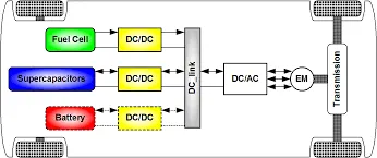
Types of Power converter:
There are four main types of power converter circuits , which are used in electric and hybrid electric vehicles...There are ,,
AC to DC Converter:
- AC to DC Converters are one of the most important in power electronics because there are lot of real applications are based on this conversions..
- The AC current DC current conversion process is known as Rectification. The Rectifier convert AC supply into the DC supply at loaad end connection..
- Normally Transformers are used to adjust the AC source to get step down transformer to reduce the volatge level to have better operation range for DC supply.Noramlly AC to DC converter converts low voltage values..
- In most of the countries , the electrical power generation and transmission are purely based on alternating current .DIfferent types of eleectrical power stations use alternators to generate electricity.
- Most of the electrical appliance which use DC current for their operation such as Television,computers,mobiles etc..
- In the case of EVs and HEVs the battery pack which operates with a DC power supply is charged at home or at a charging station both of which are supplied power inAC form from the electric grid ,, so the charges for these vehicles are an example of the AC to DC power converter..
DC to AC converter:
- A power inverter is a power electronic device or circuitry that changes direct current to alternating current .The input voltage ,output voltage and frequency ,and overall power handling depend on the design of the specific device .The inverter does not produce any power , the power is provided by the DC source ..
- A power inverters can be entirely electronic or may be a combination of mechanical effects and electronic circuitry.Static inverters do not use moving parts in the conversion process
- An inverter is a device that converts DC power to the AC power uesd in an electric vehicle motor .The inverter can change the speed at which the motor rotates by adjusting the frequency of the alternating current ..
DC to DC converter :
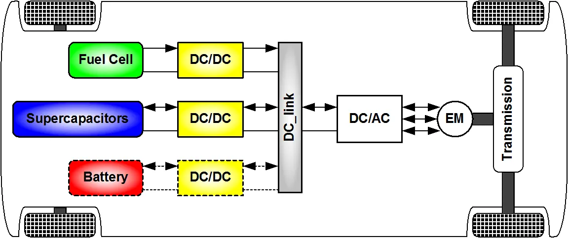
- In electric engineering , a DC to DC converter is a category of power converters and it is an eletric circuit which converts a source of direct current from one voltage level to another , by storing the input energy temporarily and then releasing that energy to the output at a different voltage ..
-
DC/DC converters can be designed to transfer power in only one direction, from the input to the output. However, almost all DC/DC converter topologies can be made bi-directional. A bi-directional converter can move power in either direction, which is useful in applications requiring regenerative braking.
1. Non-isolated converters:
The non-isolated converters type is generally used where the voltage needs to be stepped up or down by a relatively small ratio (less than 4:1). And when there is no problem with the output and input having no dielectric isolation. There are five main types of converter in this non-isolated group, usually called the buck, boost, buck-boost, Cuk and charge-pump converters. The buck converter is used for voltage step-down, while the boost converter is used for voltage step-up. The buck-boost and Cuk converters can be used for either step-down or step-up. The charge-pump converter is used for either voltage step-up or voltage inversion, but only in relatively low power applications.
2. Isolated converters:
Usually, in this type of converters a high frequency transformer is used. In the applications where the output needs to be completely isolated from the input, an isolated converter is necessary. There are many types of converters in this group such as Half-Bridge, Full-Bridge, Fly-back, Forward and Push-Pull DC/DC converters . All of these converters can be used as bi-directional converters and the ratio of stepping down or stepping up the voltage is high.
AC to AC converter:
- Ac to Ac converters is used for converting the AC waveforms with one particular frequency and magnitude to AC waveform with another frequency at another magnituide .This conversion is mainly required in case of speed controlling of machines ,for low frequency and variable voltage magnitude applications as well.
- We know that there are different types of loads that work with different types of power supplies like single phase ,three phase supply ,and the supplies can be differentiated based on the voltage and frequency range also..
- We require a paricular voltage and particular frequency for operating some special devices or machines ..for speed control of induction motors ,, AC to AC converters is used majorly for obtaining a desired AC power supply from the actual power supply ,we need some converters called AC to AC converters
2)
Vehicle Output Voltage() = Battery Voltage(V)*Duty Cycle
= 72*0.70
= 50.4 V
So, the vehicle voltage is 50.4 V
Now, Equation for Vehicle torque is :
Tv">Tv��= Vv">Vv��.KϕRa">KϕRa����-(Kϕ)2Ra">(Kϕ)2Ra(��)2��.w">w� ................ (1)
Where,
Tv">Tv��= Vehicle Torque (N-m)
Vv">Vv��= Vehicle Voltage (Volts)
w">w�= Steady State speed of Vehicle (rps)
K">K�ϕ">ϕ�= Motor Constant
Ra">Ra�� = Armature Resistance
Substituting all the values in equation 1, we get
Tv">Tv��= 50.4×0.70.5-(0.7)20.5×w">50.4×0.70.5−(0.7)20.5×w50.4×0.70.5-(0.7)20.5×�
Tv">Tv��= 70.56-0.98w2">70.56−0.98w270.56-0.98�2 .................(2)
Now, the vehicle speed torque characteristics is given as,
Tv=24.7-0.0051w2">Tv=24.7−0.0051w2��=24.7-0.0051�2 .....................(3)
At Steady State,
Eq (2) = Eq (3) ...................(4)
24.7-0.0051w2=70.56-0.98w2">24.7−0.0051w2=70.56−0.98w224.7-0.0051�2=70.56-0.98�2
0.0051w2+0.98w-45.85=0">0.0051w2+0.98w−45.85=00.0051�2+0.98�-45.85=0 ..................(5)
To solve the above eq we have to apply the QUADRATIC EQUATION formula,
x=-b±b2-4ac2a">x=−b±√b2−4ac2a�=-�±�2-4��2�
x=-0.98±0.982-4(0.0051)(-45.85)2⋅(0.0051)">x=−0.98±√0.982−4(0.0051)(−45.85)2⋅(0.0051)�=-0.98±0.982-4(0.0051)(-45.85)2⋅(0.0051)
w=">w=�=38.92 rad/sec
So, The steady-state speed of the vehicle is 38.92 rad/sec.
3)
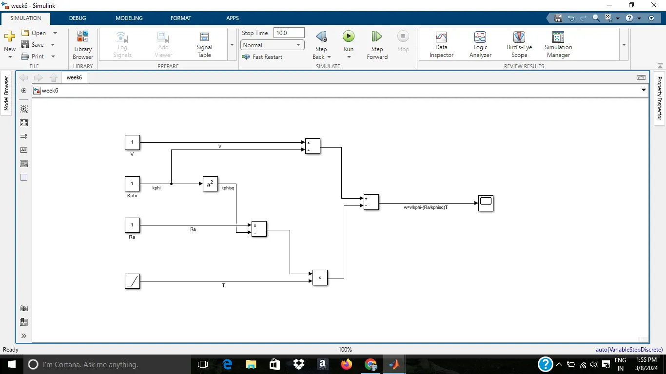
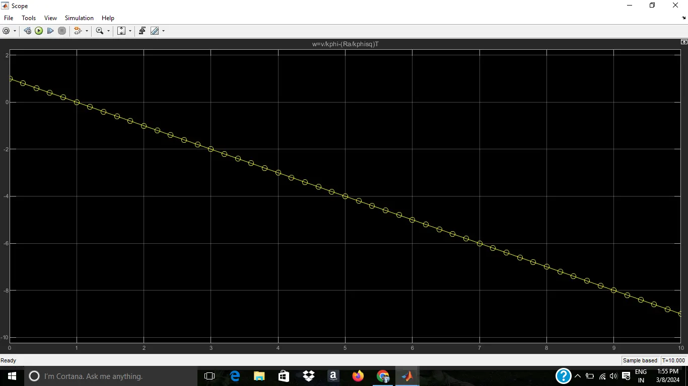
simulink model is attached as week 6
4)
Wally Ripple is a long-time proponent of electric vehicles. Prior to joining Tesla Motors, he was an engineer at AeroVironment, where he helped develop the EV1 for General Motors and was featured in the documentary movie, Who Killed the Electric Car? Wally has also worked for the Jet Propulsion Laboratory on electric vehicle battery research, among other projects. In 1968, as a Caltech undergraduate student, he built an electric car (a converted 1958 Volkswagen microbus) and won the Great Transcontinental Electric Car Race against MIT.
In the beginning, the author describes the dominance of Internal Combustion Engines(ICE) in the world of automobile industry. He explains that all engines were similar and it was up to the user to select according to their requirement. Next, the author highlights topics related to EV technology especially related to DC Brushless Motor and Induction Motor.
According to him, DC Brush Motors is replaced by either DC Brushless Motor or Induction Motor. Also, the Lead Acid Battery is replaced by lithium-ion batteries for EVs.He also quoted that there will be the future of both the technology (DC Brushless Motor and Induction Motor) depends upon their demands and uses.
DC Brushless Motor:
With brushless machines, the rotor includes two or more permanent magnets that generate a DC magnetic field (as seen from the vantage point of the rotor). In turn, this magnetic field enters the stator core (a core made up of thin, stacked laminations) and interacts with currents flowing within the windings to produce a torque interaction between the rotor and stator. As the rotor rotates, it is necessary that the magnitude and polarity of the stator currents be continuously varied – and in just the right way - such that the torque remains constant and the conversion of electrical to mechanical energy is optimally efficient. The device that provides this current control is called an inverter. Without it, brushless motors are useless motors.
The author also said that a brushless DC motor produces no starting torque when directly connected to fixed frequency utility power. They really need the aid of an inverter whose “phase” is maintained in step with the angular position of the rotor.
Advantage:-
The advantage of DC Brushless Motor is that there is low heat generation in the rotor and its cooling capacity is better as compared to Induction Motor. Also, peak point efficiency is generally higher for this drive. The DC brushless drive can also operate at unity power factor, whereas the best power factor for the induction drive is about 85%. This means that the peak point energy efficiency for a DC brushless drive will typically be a few percentage points higher than for an induction drive.
Disadvantage:-
As Machine size grows, the magnetic losses increase proportionately and part load efficiency drops. Permanent magnets are expensive and difficult to handle due to very large forces that come into play when anything ferromagnetic gets close to them.
Induction Motor:
The technology behind the induction motor is that it basically uses a 3-phase induction motor which was invented by Nikola Tesla sometime before 1889. Unlike the DC brushless rotor, the induction rotor has no magnets – just stacked steel laminations with buried peripheral conductors that form a “shorted structure.” Currents flowing in the stator windings produce a rotating magnetic field that enters the rotor. In an Induction motor current interacts with the Magnetic field generated by the stator to produce a force which is required for rotor torque.
When a 3-phase induction motor is connected to utility type 3-phase power, torque is produced at the outset. The fact that induction motors are directly compatible with conventional utility power is the main reason for their success.
Advantage:-
The induction motor does not have any magnets and in this the B field is adjustable. The motor has the ability to start under load and there is no need of an inverter. In an induction motor B field is proportionate to V/f (Voltage to frequency). This technology is used to reduce the magnetic losses and conduction losses, due to which efficiency will remain at maximum peak. This all leads to increasing the performance, induction motor is very useful and efficient for high performance.
Disadvantage:-
An induction motor cannot operate from DC Voltage it always requires an AC voltage supply. In an induction motor, the Shaft speed is proportionate to line frequency. Hence, when used with utility power they are constant speed machines. When operated from utility power, they have limited starting torque and somewhat limited running peak torque capabilities, when compared to DC-type machines.