Week-6 Challenge: EV Drivetrain
1. Which types of power converter circuits are employed in electric and hybrid electric vehicle?
2. An Electric Vehicle's powertrain with 72V battery pack in shown in the diagram below. The duty ratio for acceleration operation is 'd1' and for the braking operation the duty ratio is 'd2'.
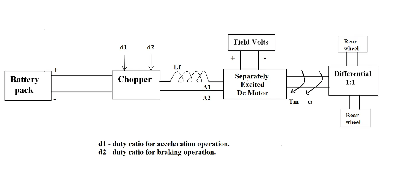
The other parameters of the electric vehicle is given below,
Motor and Controller Parameters:
Rated Armature voltage= 72 V
Rated armature current= 400 A
Ra= 0.5Ω, KΦ= 0.7 Volt second
Chopper Switching frequency= 400 Hz
The vehicle speed-torque characteristics are given by the below equation

What is EV steady state speed if duty cycle is 70%?
3. Develop a mathematical model of a DC Motor for the below equation using Simulink.
w=v/k_phi-Ra/k_phi^2*T
4. Refer to the blog on below topic:
Induction Versus DC brushless motors by Wally Rippel, Tesla
Explain in brief about author’s perspective.
AIM:
1. Which types of power converter circuits are employed in electric and hybrid electric vehicle?
2. An Electric Vehicle's powertrain with 72V battery pack in shown in the diagram below. The duty ratio for acceleration operation is 'd1' and for the braking operation the duty ratio is 'd2'.
The other parameters of the electric vehicle is given below,
Motor and Controller Parameters:
Rated Armature voltage= 72 V
Rated armature current= 400 A
Ra= 0.5Ω, KΦ= 0.7 Volt second
Chopper Switching frequency= 400 Hz
The vehicle speed-torque characteristics are given by the below equation
What is EV steady state speed if duty cycle is 70%?
3. Develop a mathematical model of a DC Motor for the below equation using Simulink.
w=v/k_phi-Ra/k_phi^2*T
4. Refer to the blog on below topic:
Induction Versus DC brushless motors by Wally Rippel, Tesla
Explain in brief about author’s perspective.
1.Q:
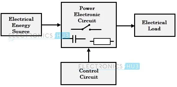
Power converter: From below image power converter can be explained as main link between electrical energy source and electrical load. To enhance life and reliability of load it is necessary to give the power as per their requirements and these requirements gets fulfiled with the help of power converters.
Control circuit helps for controlling the logic set by user to run any electric load.
Power circuits includes SCR's, IGBT, MOSFET etc such kind of electronic components whose switching frequency is much more faster than normal transistion. These switching frequency preserves the load as well as power is not wasted.
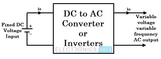
DC to AC converter or Inverter:
This converter converts fixed DC voltage into variable/fixed voltage and variable/fixed frequency AC output.
It is also known as inverters.Two types of inverters are available based on voltage classificiation which is Single phase and Three phase.
Thyristors are used to invert the voltage level.
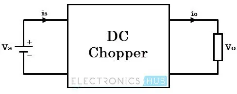
3. DC to DC converter or Chopper:
This converter converts fixed DC input to variable/fixed DC output with change in magnitude. It is also knwn as Choppers.
Step up chopper produces an average output level higher than input level where as Step down chopper prduces an average output level lesser than input.
This converter uses thyristors in such a manner which controls the voltage level as per load requirements.
4. AC to AC converters:
This converter controls the RMS value of output voltage at constant frequency.
Common applications of these converters is starting of AC motors and controlling power to heaters.
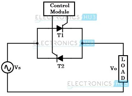
Here two thyristors in anti parallel fashion are used for controlling.
Electric vehicle drive system:
Two converters are mainly used in EV's or HEV's those are DC to DC converters and DC to AC converters.
2.Q
given data
battery pack voltage =72 v
Armature voltage= 72 V
armature current= 400 A
Ra= 0.5Ω
KΦ= 0.7 Volt second
Chopper Switching frequency= 400 Hz
The vehicle speed-torque characteristics = Tv=24.7+(0.0051)w^2
duty cycle is d=70%
to convert per to fricition=pertage/100
d= 70/100
d=0.7
we know that vehicle output voltage =battery pack voltage *duty cycle
Vv = 72*0.7
Vv = 50.4
vehicle output voltage is Vv = 50.4
we know that torqye equation =T= V-ra/(k_phi)-k(_phi^2)*speed
Tv=Vv*(k_phi/ra)-(k_phi^2/ra)*w
=50.4*0.7/0.5-(0.7)^2/0.5*w
= 70.56-0.98w
Tv=70.56-0.98w
given that Tv= 24.7+(0.0051)w^2 is substitue in above equation
24.7+(0.0051)w^2=70.56-0.98w
0.0051w^2+0.98w=70.56-24.7
0.0051w+0.98=45.86
0.0051+0.98-45.86=0
the above equation is ax^2+bx+c so that -b+or-squroot*(b^2-4ac)/2a
x=-0.98+or-squreroot*0.98^2-4*0.0051*(-45.86)/2*0.0051
x=-0.98+or-squreroot*0.9604-(-0.935544)/0.0102
x=-0.98+or-squreroot*1.921584/0.0102
x=-0.98+or-1.37840/0.0102
x1=-0.98+1.376932823/0.0102 x2=-0.98-1.376932823/0.0102
x1=0.396932823/0.0102 x2=-2.356932823/0.0102
x1= 39.91 x2= -231.071
negitve is negliable so that considering x1=39.91 rps
the steady state speed of EV at 70% of duty cycle is 39.91 rps
top convert rps to rpm = rps * 60
rpm = 39.91*60
rpm = 2394.6 rpm
3.Q :
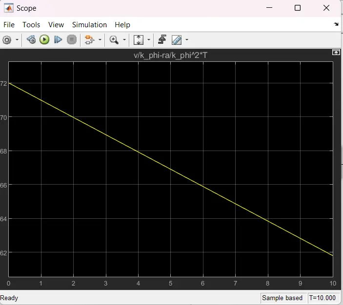
given that equation is w=v/(k_phi)-ra/(k_phi^2)*T
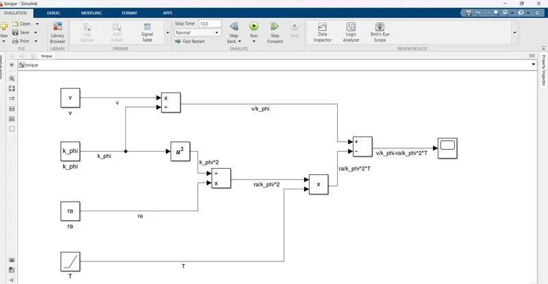
output is scope is
4.Q:
Wally Ripple is a long-time proponent of electric vehicles. Prior to joining Tesla Motors, he was an engineer at AeroVironment, where he helped develop the EV1 for General Motors and was featured in the documentary movie, Who Killed the Electric Car? Wally has also worked for the Jet Propulsion Laboratory on electric vehicle battery research, among other projects. In 1968, as a Caltech undergraduate student, he built an electric car (a converted 1958 Volkswagen microbus) and won the Great Transcontinental Electric Car Race against MIT.
In the beginning, the author describes the dominance of Internal Combustion Engines(ICE) in the world of automobile industry. He explains that all engines were similar and it was up to the user to select according to their requirement. Next, the author highlights topics related to EV technology especially related to DC Brushless Motor and Induction Motor.
According to him, DC Brush Motors is replaced by either DC Brushless Motor or Induction Motor. Also, the Lead Acid Battery is replaced by lithium-ion batteries for EVs.He also quoted that there will be the future of both the technology (DC Brushless Motor and Induction Motor) depends upon their demands and uses.
DC Brushless Motor:
With brushless machines, the rotor includes two or more permanent magnets that generate a DC magnetic field (as seen from the vantage point of the rotor). In turn, this magnetic field enters the stator core (a core made up of thin, stacked laminations) and interacts with currents flowing within the windings to produce a torque interaction between the rotor and stator. As the rotor rotates, it is necessary that the magnitude and polarity of the stator currents be continuously varied – and in just the right way - such that the torque remains constant and the conversion of electrical to mechanical energy is optimally efficient. The device that provides this current control is called an inverter. Without it, brushless motors are useless motors.
The author also said that a brushless DC motor produces no starting torque when directly connected to fixed frequency utility power. They really need the aid of an inverter whose “phase” is maintained in step with the angular position of the rotor.
Advantage:-
The advantage of DC Brushless Motor is that there is low heat generation in the rotor and its cooling capacity is better as compared to Induction Motor. Also, peak point efficiency is generally higher for this drive. The DC brushless drive can also operate at unity power factor, whereas the best power factor for the induction drive is about 85%. This means that the peak point energy efficiency for a DC brushless drive will typically be a few percentage points higher than for an induction drive.
Disadvantage:-
As Machine size grows, the magnetic losses increase proportionately and part load efficiency drops. Permanent magnets are expensive and difficult to handle due to very large forces that come into play when anything ferromagnetic gets close to them.
Induction Motor:
The technology behind the induction motor is that it basically uses a 3-phase induction motor which was invented by Nikola Tesla sometime before 1889. Unlike the DC brushless rotor, the induction rotor has no magnets – just stacked steel laminations with buried peripheral conductors that form a “shorted structure.” Currents flowing in the stator windings produce a rotating magnetic field that enters the rotor. In an Induction motor current interacts with the Magnetic field generated by the stator to produce a force which is required for rotor torque.
When a 3-phase induction motor is connected to utility type 3-phase power, torque is produced at the outset. The fact that induction motors are directly compatible with conventional utility power is the main reason for their success.
Advantage:-
The induction motor does not have any magnets and in this the B field is adjustable. The motor has the ability to start under load and there is no need of an inverter. In an induction motor B field is proportionate to V/f (Voltage to frequency). This technology is used to reduce the magnetic losses and conduction losses, due to which efficiency will remain at maximum peak. This all leads to increasing the performance, induction motor is very useful and efficient for high performance.
Disadvantage:-
An induction motor cannot operate from DC Voltage it always requires an AC voltage supply. In an induction motor, the Shaft speed is proportionate to line frequency. Hence, when used with utility power they are constant speed machines. When operated from utility power, they have limited starting torque and somewhat limited running peak torque capabilities, when compared to DC-type machines.