Week-6 Challenge: EV Drivetrain
1. Which types of power converter circuits are employed in electric and hybrid electric vehicle?
ANS :
Power Electronic Converters:
- The AC to DC converter known as the rectifier,
- The AC to AC converter or frequency changer,
- The DC to DC voltage or current converter,
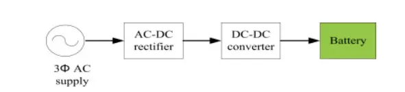
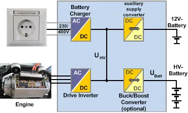
In Electric and Hybrid Electric Vehicles (EV/HEV), the power electronic converters are considered as the key elements that interface their power sources to the drivetrain of the EVs. In order to design highly efficient converters for the EV’s power system, advanced DC/DC and DC/AC converters are required to adapt the output voltage and current levels with high power quality.
The 3 types of converters which are widely used in an Electric Vehicle are:
AC – DC Converter (On Board Charger): 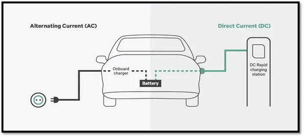
On-board charger/discharger systems are those which are placed on-board the EV, while off-board charger/discharger systems are those which are placed outside the EV [54,55]. On-board systems are attractive since they provide the EV owners with the flexibility to charge/discharge their vehicles wherever an electric power outlet is available. Moreover, on-board systems secure accurate voltage matching for the EV battery. The grid voltage is generally fixed, while the battery voltage is not and varies from EV to EV. The on-board systems are precisely designed by EV manufacturers for each vehicle to meet the specific voltage requirements of the battery and the grid. The same is not true with off-board systems, which are designed to support a wide range of EV battery voltages. However, weight, volume and cost of an EV increases by the presence of an on-board charger/discharger system [18]. The current focus is to achieve fast charging/discharging, which demands high power dense converter systems. This may characterize the on-board systems as incompetent for fast charging/discharging (SAE Level 3) due to their lower power handling capability compared to off-board systems. Nevertheless, high power handling capability is also desired for an off-board system to minimize its footprint, weight and cost. On-board systems, however, reduce the grid charging/discharging infrastructure requirement to simple high-power outlets that can be used to charge or discharge the EVs, hence reducing the cost of these off-board outlets. Moreover, the risk of vandalism is avoided with on-board systems [54]. It can be concluded that either the EV owners or the utility operators who facilitate G2V/V2G operation must incur the cost of the charging/discharging facilities.AC to DC converters are most commonly used in Plug-in Hybrid Electric Vehicles (PHEV) & Plug-in Electric Vehicles (PEV). These vehicles get their propulsion power from an external electricity source (charging stations) which is alternating current. The battery needs to be charged using a direct current source. For this purpose, AC to DC converter is employed in a PHEV & PEV.
DC – DC Converter: -
DC-DC converters can be used to interface the elements in the electric power train by boosting or chopping the voltage levels. By introducing DC/DC converters one can choose the voltage variation of the devices and the power of each device can be controlled. The power of the DC/DC converter depends on the characteristics of the vehicle such as top speed, acceleration time from 0 to 100 Km/h, weight, maximum torque, and power profile (peak power, continuous power).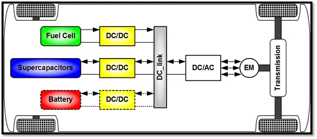
DC – AC Converter (Inverter): -
The DC/AC converter is required to convert the dc power to a suitable ac power for the electrical machine. The power output from battery pack (DC current) is converted using inverter to be used in electric motor (AC current).
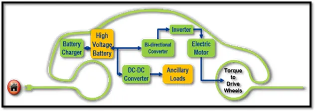 DC-to-AC Converters are one of the most important elements in power electronics. This is because there are a lot of real-life applications that are based on these conversions. The electrical circuits that transform Direct current (DC) input into Alternating current (AC) output are known as DC-to-AC Converters or Inverters. They are used in power electronic applications where the power input pure 12V, 24V, 48V DC voltage that requires power conversion for an AC output with a certain frequency.
References: - https://www.intechopen.com/books/electric-vehicles-modelling-and-simulations/dc-dc-converters-for-electric-vehicles#B14
ANS 2 :
The other parameters of the electric vehicle is given below,
Motor and Controller Parameters:
Rated Armature voltage= 72 V
Rated armature current= 400 A
Ra= 0.5Ω, KΦ= 0.7 Volt second
Chopper Switching frequency= 400 Hz
The vehicle speed-torque characteristics are given by the below equation

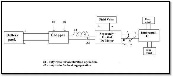
What is EV steady state speed if duty cycle is 70%?
Given: -
The following input parameters are given: -
Battery pack voltage (V) = 72V
Rated armature current = 400 A
Armature Resistance (Ra) = 0.5Ω
Motor constant (KΦ) = 0.7
Chopper Switching frequency= 400 Hz
Duty Cycle = 70%ω">ω
Solution: -
Vehicle Output Voltage (Vv) is given by: -
Vv = Battery Voltage (V) * Duty Cycle
Vv = 72 * 0.70
Thus, Vehicle voltage = 50.4V
Now, Equation for Vehicle torque is given by: -
Tv=(Vv-ω.K∅)⋅K∅Ra">Tv=(Vv−ω.K∅)⋅K∅Ra
Where;
Tv">Tv
= Vehicle Torque (N-m)
Vv">Vv
= Vehicle voltage (Volts)
ω">ω
= steady state speed of vehicle (rps)
K∅">K∅
= Motor constant
Ra">Ra
= Armature Resistance
Substituting all these values in equation, we get:
Tv=(50.04-0.7⋅ω)⋅0.70.5">Tv=(50.04−0.7⋅ω)⋅0.70.5
Tv=70.56-0.98⋅ω">Tv=70.56−0.98⋅ω
Tv=24.7+0.0051⋅ω2">Tv=24.7+0.0051⋅ω2
Solving these two equations,
70.56-0.98⋅ω=24.7+0.0051⋅ω2">70.56−0.98⋅ω=24.7+0.0051⋅ω2
We get a quadratic equation:
0.0051⋅ω2+0.98⋅ω-46.94=0">0.0051⋅ω2+0.98⋅ω−46.94=0
Since quadratic equation, we get two values of ;
ω">ω
= 38.85 rad/s and ω">ω
= -230.95 rad/s
We take the positive value;
Steady state speed of vehicle = = 38.85 rad/s
ANS 3 : From observing the equation given, we know it is the formula for finding the steady state speed of the EV. Hence the output Simulink model for this equation gives the graphical and figure value of speed of the EV.
Mathematical model of DC motor speed-torque characteristics is shown below: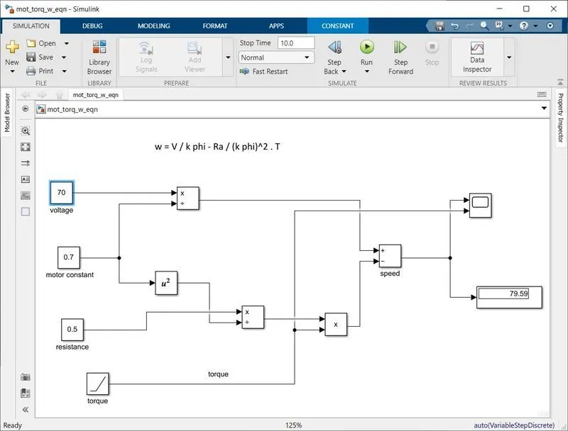
Different Blocks used in simulation :
Constant block – voltage, motor constant, armature resistance.
Multiplication-division block, product block, math operation (for power) block to square the motor constant and adder block to calculate the speed.
Ramp block - torque input, scope and display.
The connections are made as shown in the figure shown above. The supply voltage is taken as 70 voltage, motor constant and the armature resistance are assumed as 0.7 volt-second and 0.5 ohms. Since the torque is taken as a ramp signal it increases linearly, proportional to the simulation time.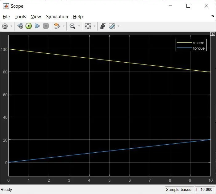 From the graph it is verified that at 10 Nm torque the speed is approximately 80 rad / sec. We can also see that for every value of the torque increasing from 0, the speed decreases and are linear in nature. Hence we can conclude that the torque and speed characteristics of the DC motor is inversely proportional.
ANS 4 :
In Wally Rippel blog he discussed about So two technologies i.e. DC brushless and induction.How do they work? What differentiates them? And what do they have in common.
In starting he said one size does not fit all means in that odious word engines are of the different types some years ago some thought to try to figure out which is best engine and that should be in production but his thoughts got failed as there is no only one best with the different requirements there are different type of engines so this also implies in case of brushless DC and induction motor all are alike and its up to the user to select one according to their requirements due to the imprising technology there has been alternative found and then such as lead acid batteries DC brush motors and contact controllers have been replaced by Lithium batteries brushless DC or induction motors and inverters one tho their has been various replacement brushless DC and induction motors are playing a major role till date to the construction and working of the brushless motors and induction motors are being discussed the status for the three phase induction motor and the DC brushless motor are Virtually identical he said both have three sets of distributed windings that are inserted within the status Core. Both drives use three face modelling inverters the only difference are the routers and the inverter controls the pros and cons of both brusless DC motors and induction motors are being discussed here the advantage of brushless DC Motors are much less rotar it is generated the peak point efficiency will be a few percent hire then the induction motor that disadvantages are the Machines size grows the magnetic losses increases proportionately and part load efficiency drops permanent rotors are also difficult to handle due to very large forces that come into play when anything ferromagnetic gets come close to them . induction motor has some advantages the motor has no magnets the motor can start under no load condition the disadvantages are they cannot open in DC. When operated with utility power they have limited starting torque and Limited dark capabilities when compared to DC type machines by saying Still No Winner in his blog he concludes that DC brushless drives will likely continue to dominate in the hybrid and coming plug-in hybrid markets, and that induction drives will likely maintain dominance for the high-performance pure electrics. And The hardware is common for both drives could mean that we will see induction and DC brushless live and work side by side during the coming golden era of hybrid and electric vehicles.
His conclusion was that DC brushless drives will likely continue to dominate in the hybrid and coming plug-in hybrid markets, and that induction drives will likely maintain dominance for the high-performance pure electrics. The question was what will happen as hybrids become more electrically intensive and as their performance levels increase? The fact that so much of the hardware is common for both drives could mean that he will see induction and DC brushless live and work side by side during the coming golden era of hybrid and electric vehicles.