Week-6 Challenge: EV Drivetrain
1, Which types of power converter circuits are employed in electric and hybrid electric vehicle
Ans:
Power Converter:
The task of a power converter is to process and control the flow of elctric energy by supplying voltage and current in a farm that is optimaly suited for user loads. the larger number of automobiles in use around the world has caused and continues to cause serious problems of environment and human life. Air pollution, global warming and the rapid depletion of the earth petroleum resources are new serious problems. Electric vehicles, Hybrid Electric vehicles, and fuelcell elctric vehicles have been typically proposed tp to replace conventional vehicles in the near future.
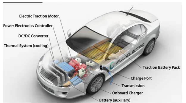
An Electric vehicle is a vehicle that uses a combination of differnt energy sources, Fuel cells, Batteries and super capacitor to power on electric dive system. In EV, one or more energy storage devices assist the main energy source. Therby the system cost, mass and volume can be decresed and significant better performance can be obtanied. Two often used energy storage devices are batteries and suoer capacitor
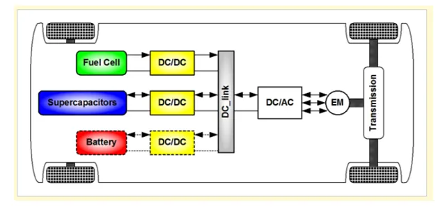
DC-AC = Inverter
DC – DC = Converter
Battery
MOTOR
Electric Vehicle comprises of 2 main power converter components they are
DC – DC Converter
DC – AC Inverter
DC-DC CONVERTER:
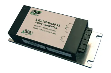
DC-DC converters can be used to interface the elements in the electric power train by boosting or chopping the voltage levels.
The different configurations of EV power supply show that at least one DC/DC converter is necessary to interface the FC, the Battery or the Super capacitors module to the DC-link.
The amount of power flow between the input and the output can be controlled by adjusting the duty cycle (ratio of on/off time of the switch). Usually, this is done to control the output voltage, the input current, the output current, or to maintain a constant power.
They are used in battery charging and Regenerative braking
DC/DC converter topologies can be used as bi-directional. A bi-directional converter can move power in either direction, which is useful in applications requiring regenerative braking.
Non-isolated converters
The non-isolated converters type is generally used where the voltage needs to be stepped up or down by a relatively small ratio and when there is no problem with the output and input having no dielectric isolation. These are main types of converter in this non-isolated group, usually called the buck, boost, buck-boost and Cuk converters.
The buck converter is used for voltage step-down,
The boost converter is used for voltage step-up.
The buck-boost and Cuk converters can be used for either step-down or step-up.
Isolated converters
Usually, in this type of converters a high frequency transformer is used. In the applications where the output needs to be completely isolated from the input, an isolated converter is necessary. There are many types of converters in this group such as Half-Bridge, Full-Bridge, and Fly-back, Forward and Push-Pull DC/DC converters. All of these converters can be used as bi-directional converters and the ratio of stepping down or stepping up the voltage is high.
Electrical Vehicle Converter Requirements:
Small volume,
Low electromagnetic interference,
Low current ripple drawn from the Fuel Cell or the battery,
The step up function of the converter,
High efficiency
INVERTERS (DC-AC)
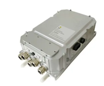
It Converts direct current (DC) from the battery to alternating current (AC) to be used by other devices such as the traction motor
Inverter can used to control speed of the motor by adjusting the frequency of the Alternating current
Inverters have capability to change the torque power by adjusting the alternating current parameters
NEED OF INVERTER IN ELECTRIC CARS:
It inverts DC charge to AC charge for driving the motor and then the opposite during regenerative braking. An equally important job of the inverter is to control the switching of the static coils in the motor to create a revolving magnetic field, like a merry-go-round, to spin the motor's rotor.
2, An Electric Vehicle's powertrain with 72V battery pack in shown in the diagram below. The duty ratio for acceleration operation is 'd1' and for the braking operation the duty ratio is 'd2'.
Ans :
MOTOR AND CONTROLLER PARAMETRS:
Rated Armature voltage= 72 V
Rated Armature current= 400 A
Ra= 0.5 Ω
KØ= 0.7 Voltage Seconds
Chopper Switching frequency= 400 Hz
Vehicle Speed Torque equation is given as:
Tv: 24.7+ (0.0051)w^2
AIM:
Given Duty cycle = 70 % = 0.7
Voltage = Rated Armature Voltage * Duty Cycle
= 72*0.7 = 50.4 Volts
T-motor Torque󠅶
V-Voltage
Ra-Armature Resistance
KØ-Motor constant
w -Angular Speed of Motor
Torque-Speed characteristics of DC motor:
Tm = (V KØ/Ra)-(( (KØ)^2/Ra)*w
Tm = ((50.4)*0.7)/0.5 – ((0.7)^2/(0.5))*w
Tm = 70.56 – 0.98 w _____EQ (1)
Tv = 24.7 + (0.0051) w^2_______EQ (2)
Equating the above the equations (1) & (2)
24.7 + (0.0051)w^2 = 70.56 – 0.98
So we get quadratic equation
0.0051 w ^2 + 0.98 w – 45.86 = 0
In order to find roots to Solve the above equation which is in form of quadratic equation
ax^2 + bx + c = 0 by using these formule:
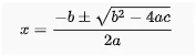
Substituting the equations values in above formula
w = 0.98± ((√ (0.98)^2 – 4*0.0051 * 45.8) / 2*0.0051
Here we get w = 38.92 rad/sec or 231.02 rad /sec
Steady state of the angular speed is 38.92 rad /sec
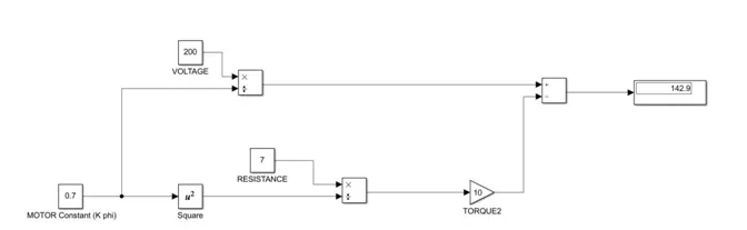
3, Develop a mathematical model of a DC Motor for the below equation using Simulink.
Ans :
4, Induction Versus DC Brushless Motors
His prospective about electric vehicle future technology cannot be predicted easily. The gas powered vehicles engines are not all same and there is no best engine type people choose according to their requirements such as price and performance these also comes under electric vehicles but in nearby future EV drives may get stability.
The author said that both induction motor and DC brushless motor have advantages as well as disadvantages and he explained about basic construction of both the motors
Induction motor does not have permanent magnets and it is connected to 3-phase utility power, torque is produced at the outset the motor has ability to start under load so the inverter is not needed so it has ability to compatible with the conventional vehicles. If induction motor size increases the losses will not increase. With the help of induction motor drive we can achieve required high performance.
Limitations of induction motor is it requires source power as AC it will not operate in DC. This motor has limited starting torque and limited running peak torque capabilities as shaft speed is proportionate to line frequency so in order to overcome such draw backs it requires an inverter and feedback signal and speed variation depends upon the frequency input. It is hard to control
In DC brushless motors the strength of magnetic field is adjusted When maximum torque is required, especially at low speeds, the magnetic field strength should be maximum – so that inverter and motor currents are maintained at their lowest possible values. This minimizes the I² R losses
Where DC brushless machines requires permanent magnets which is cost efficient. Construction of DC brushless motor is costly compared to induction motor because of magnets
He finally said that DC brushless motors will dominance in HEV and PHEV
And Induction motor is highly preferred in PURE EV
author’s perspective
In the blog of induction and DC brushless motor, the author has mentioned about positives and negative side of both the induction and DC motor. In the blog, the basic construction of both the induction and DC brushless motor is explained.
In case of DC brushless motor, permanent magnets are used which produces a rotating magnetic field. This magnetic field when induces a current in the conductor. This current results in force generation in the rotor and this results in rotation of the rotor.
Whereas in case of induction motor, the current is supplied to the stator which results in the generation of emf, when this emf comes in contact with the rotor which is generally a squirrel cage type, this results in current induced in the rotor. Unlike the DC motor, the rotor consists of conductors plates and placed in a cage-like structure. This also consists of bars around them in which current get induced and the rotor starts rotating.
One of the main differences is that much less rotor heat is generated with the DC brushless drive. Rotor cooling is easier and peak point efficiency is generally higher for this drive. It is mentioned that the DC brushless can drive at unit power factor, whereas the best power factor for the induction drive is about 85%.
In case of DC brushless motor, the strength of the magnetic field is adjustable. When at low speed the maximum torque is required magnetic field should be maximum, i.e. inverter and motor current maintained at their lowest optimize efficiency. Whereas there is no such adjustment in case of induction motor. As machine size grows, magnetic losses increases proportionally and part load efficiency drops. In case of induction motor, as machine size grows, losses do not necessarily grow. The construction of DC brushless motor is costly compared with an induction motor, due to the use of permanent magnets.
However thought the speed variation of induction motor depends upon the frequency input, it is difficult to control.