Week-6 Challenge: EV Drivetrain
PROJECT: EV DRIVETRAIN
OBJECTIVE:
1. Which types of power converter circuits are employed in electric and hybrid electric vehicle?
2. An Electric Vehicle's powertrain with 72V battery pack in shown in the diagram below. The duty ratio for acceleration operation is 'd1' and for the braking operation the duty ratio is 'd2'.
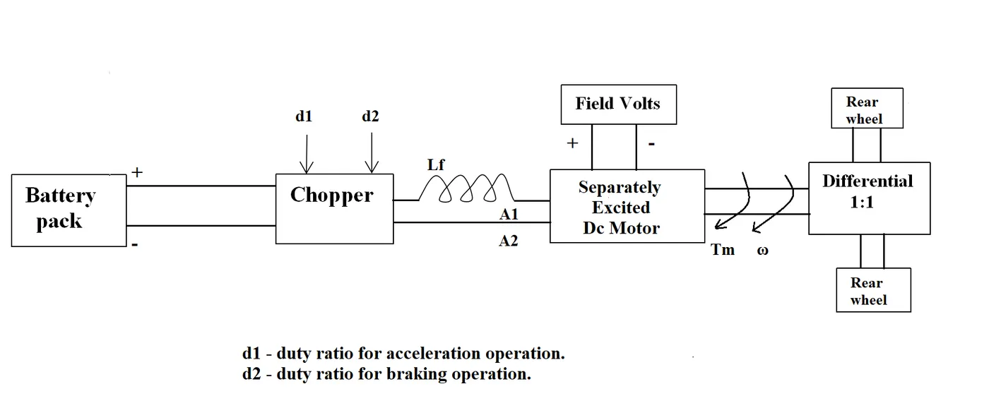
The other parameters of the electric vehicle is given below,
Motor and Controller Parameters:
Rated Armature voltage= 72 V
Rated armature current= 400 A
Ra= 0.5Ω, KΦ= 0.7 Volt second
Chopper Switching frequency= 400 Hz
The vehicle speed-torque characteristics are given by the below equation

What is EV steady state speed if duty cycle is 70%?
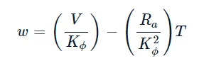
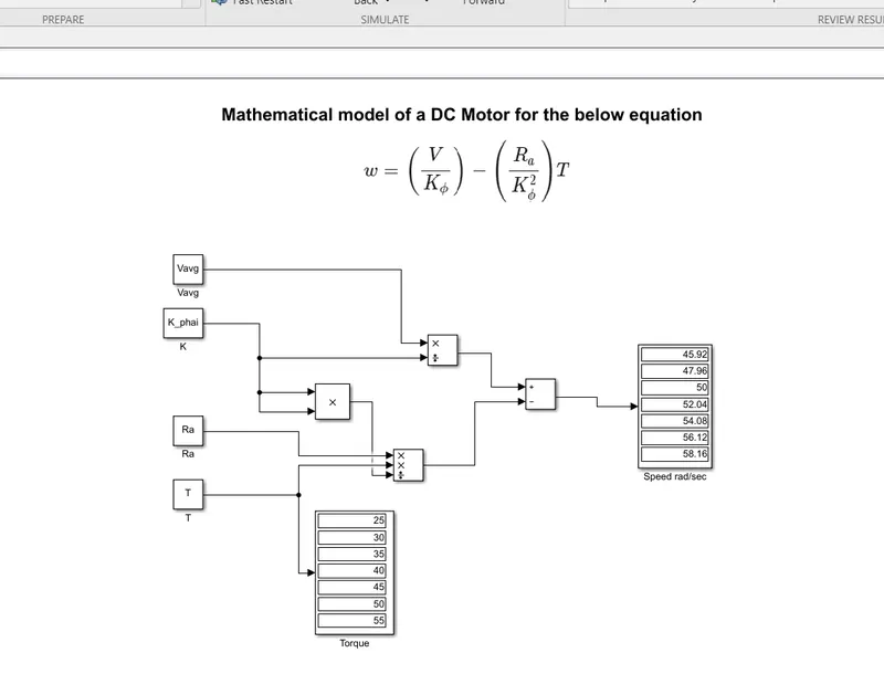
3. Develop a mathematical model of a DC Motor for the below equation using Simulink.
ω= V/Kϕ -Ra/Kϕ^2 .T
4. Refer to the blog on below topic:
Induction Versus DC brushless motors by Wally Rippel, Tesla
Explain in brief about author’s perspective.
SOLUTION:
1. Which types of power converter circuits are employed in an electric and hybrid electric vehicle?
Power Converter:
The use of power electronics is conversion and control of electric power. An electro-mechanical device for converting the form of electrical energy is a power converter. A power converter can adjust the voltage or frequency of the current, convert alternating current (AC) into direct current (DC), or do any combination of these things.
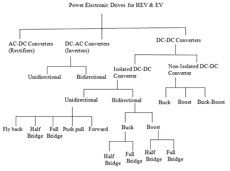
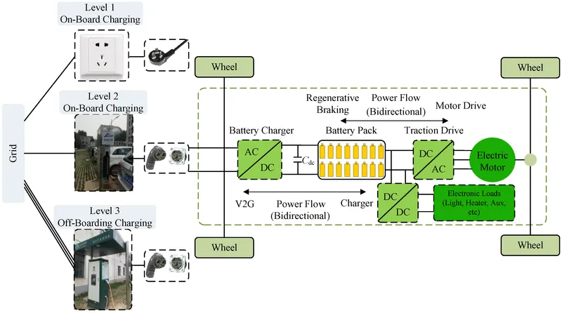
The three different power converter circuit types that are used in EVs and HEVs are listed below:
- AC to DC (Rectifier)
- DC to AC (Inverter)
- DC to DC
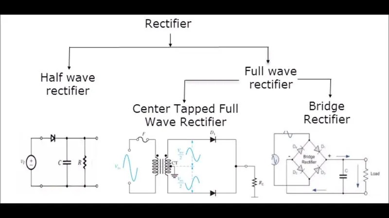
1. AC to DC (Rectifier):
It is an electrical device called a rectifier changes current from alternating current (AC), which periodically flips direction, into direct current (DC), which only flows in one direction. Rectification refers to the action of "straightening" the current's direction.
APPLICATIONS
1. In electric vehicles, a boost converter charges the battery (EV). A bridge rectifier is used in a traditional OBC (onboard charging system) to convert the input AC voltage to DC, although this method has significant conduction, as well as switching losses and heating problems during rectification.
2. Rectifiers have a wide range of applications, although they are frequently used as parts of DC power supply and high-voltage direct-current power transmission systems.
3. Rectification can be used for purposes other than producing direct current for use as a power source.
4. As mentioned, radio signal detectors function as rectifiers.
5. Flame rectification is employed in gas heating systems to find a flame.
6. An inverter is a more complex circuit that performs the opposite function, that is converting DC to AC.
2. DC to AC (Inverter):
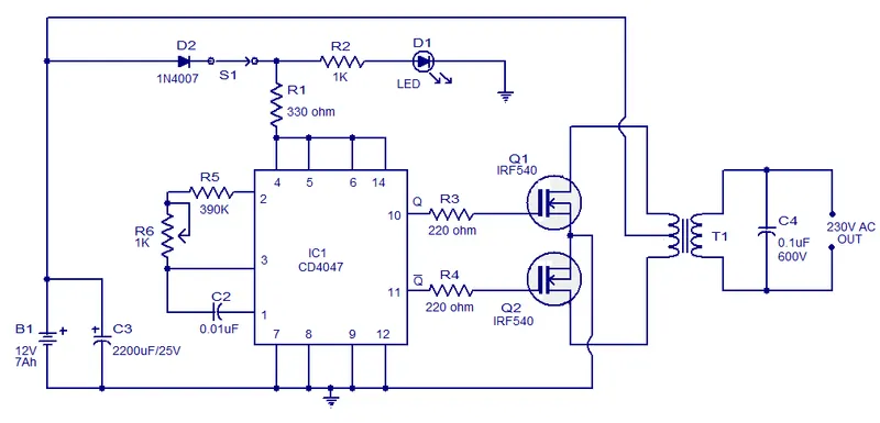
An electric vehicle motor uses an inverter to convert DC power to the AC power it needs to run. By altering the alternating current's frequency, the inverter can modify the motor's rotational speed. By changing the signal's amplitude, the motor's power or torque can also be increased or decreased.
The exact gadget used determines the produced AC frequency. In contrast to "converters," which were once substantial electromechanical devices converting AC to DC, inverters perform the opposite.
The design of the particular device determines the input voltage, output voltage and frequency, and total power handling. The power is given by the DC source, not the inverter, which does not generate any energy.
Simple Inverter Circuit:
3. DC to DC converter
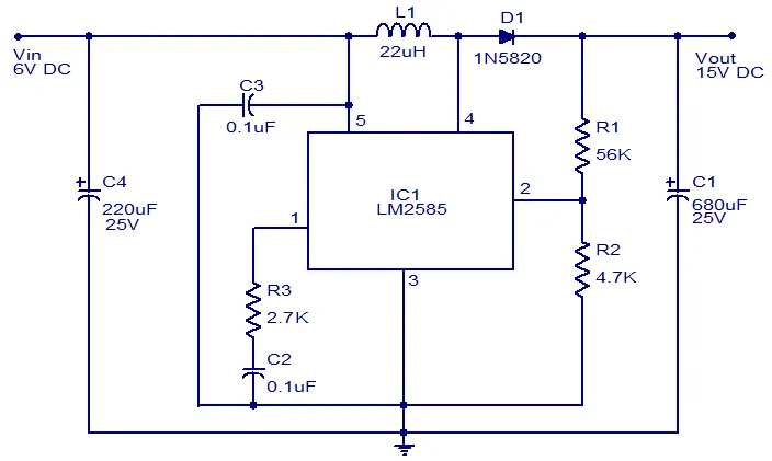
A DC-to-DC converter is an electrical or electromechanical device that changes the voltage level of a direct current (DC) source. It is an approach to converting electric power. Low to extremely high power levels (tiny batteries) (high-voltage power transmission).
Uses:
In electric vehicles (EVs) and hybrid electric vehicles, DC-to-DC converters transform dc power from an internal 200-800V high voltage battery into lower dc voltages (48V or 12V) to power headlights, interior lights, wiper and window motors, fans, pumps, and a variety of other systems (HEV).
Portable electronic gadgets that are largely powered by batteries, such laptop computers and cell phones, employ DC-to-DC converters.
These electrical devices frequently have multiple sub-circuits, each of which has a different voltage demand from what is provided by the battery or an external supply (sometimes higher or lower than the supply voltage).
Additionally, as the battery's reserves of energy are depleted, its voltage drops. Instead of needing numerous batteries to achieve the same goal, switched DC to DC converters provide a way to boost the voltage from a partially decreased battery voltage while conserving space.
Power optimizers are DC-to-DC converters created to enhance the amount of energy harvested by solar and wind power systems.
Simple DC-to-DC converter circuit:
2. An Electric Vehicle's powertrain with 72V battery pack in shown in the diagram below. The duty ratio for acceleration operation is 'd1' and for the braking operation the duty ratio is 'd2'.
The other parameters of the electric vehicle is given below,
Motor and Controller Parameters:
Rated Armature voltage= 72 V
Rated armature current= 400 A
Ra= 0.5Ω, KΦ= 0.7 Volt second
Chopper Switching frequency= 400 Hz
The vehicle speed-torque characteristics are given by the below equation
What is EV steady state speed if duty cycle is 70%?
Rated Armature voltage (V)= 72 V
Rated armature current= 400 A
Ra= 0.5Ω,
KΦ= 0.7 Volt second
Chopper Switching frequency= 400 Hz
Duty cycle (dc)= 70% = 0.7
The vehicle speed-torque characteristics are given by the below equation
The Average Voltage is the product of the battery voltage and the duty cycle.
Average voltage, Vs=V×dc
Vs=72×0.7=50.4 V
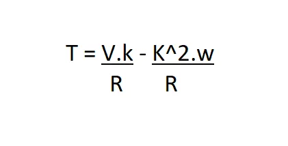
As the torque formula is given, we need to find the speed in rad/sec. Use the other expression available which is given below:
T = torque
V = armature voltage
R = resistance
w = speed rad/sec
Compare the two equations:
24.7 + 0.0051*w^2 = ((v*k)/R) - ((k^2)*w/R)
24.7 + 0.0051*w^2 = (72*0.7*0.7)/0.5 - (0.7^2/0.5)*w = 24.7 + 0.0051*w^2
70.56 - 0.98*w = 24.7 + 0.0051*W^2
w^2 + 192.15*w - 8992.15 = 0
In order to find the roots use following formula

As the speed value can not be negative
w = 38.95 rad/sec
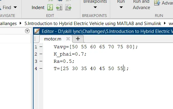
3. Develop a mathematical model of a DC Motor for the below equation using Simulink.
4. Explain in brief the author’s perspective. Refer to the blog below topic:
Induction Versus DC brushless motors by Wally Rippel, Tesla
DC Brushless Devices
The size and polarity of the stator current will continuously change during the electrical and mechanical conversion while the rotor is revolving, ensuring that the torque remains constant and that maximum efficiency is attained.
Induction Motor:
Nikola Tesla created the three-phase induction motor before 1889. The DC brushless motor and the three-phase induction motor use nearly identical stators. In the stator core of both, there are three sets of dispersed windings. The rotor is where the two machines' primary differences lies.
The induction rotor has no magnets, in contrast to the DC brushless rotor. They recently constructed a shorted structure out of steel laminations layered on top of buried peripheral wires. A revolving magnetic field is created by currents flowing in the stator windings and enters the rotor. The difference between the electrical frequency that is being applied and the rotational frequency of the rotor itself determines the frequency of this magnetic field as perceived by the rotor. Due to the disparity in rotor and electrical frequency speeds, an induced voltage is present across the shorted structure. There is a speed difference because the currents generated within the rotor conductors are roughly proportional to the voltage. Last but not least, these currents generate forces as they interact with the original magnetic field.
When a 3-phase induction motor is linked to 3-phase power of the utility type, torque is created right away. The motor can start while under load. Inverters are not required. The key factor influencing induction motors' success is the fact that they work well with traditional utility power. In contrast, when connected directly to fixed frequency utility power, a brushless DC motor doesn't generate any beginning torque. They truly require the assistance of an inverter whose phase is kept in line with the rotor's angular position.
Differences:
The majority of hybrid electric vehicles now use brushless drives, he continued, when formerly there were only a few. The control is where there is a distinction between brushless and inverter controllers. The Dc brushless requires a position sensor but an induction motor requires only a speed sensor. Less rotor heat is generated in DC brushless drive and Rotor cooling is easier and peak point efficiency is generally higher.
While the power factor of an induction drive is 85%, that of a DC brushless drive is one. While induction drives experience no rise in losses with machine size, DC Brushless machines experience an increase in magnetic losses and a fall in part-load efficiency. Induction drives are appropriate for activities requiring high performance.
Finally, we can learn that the author predicts that the induction drive will continue to rule the high performance pure electric vehicle markets while the DC brushless will continue to rule the hybrid electric vehicle markets. There is now no clear winner between the two because each has strengths and weaknesses and excels in a particular area.