Week-6 Challenge: EV Drivetrain
Q 1. Which types of power converter circuits are employed in electric and hybrid electric vehicle?
ANSWER: -
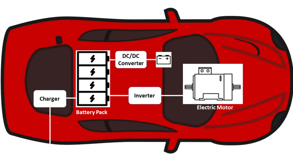
A power converter is an electrical circuit that changes the electric energy from one form into the desired form optimized for the specific load. A converter may do one or more functions and give an output that differs from the input. It is used to increase or decrease the magnitude of the input voltage, invert polarity, or produce several output voltages of either the same polarity with the input, different polarity, or mixed polarities such as in the computer power supply unit.
The converter acts as the link or the transforming stage between the power source and the power supply output. There are several kinds of converters based on the source input voltage and the output voltage and these falls into four categories namely the AC to DC converter known as the rectifier, the AC to AC clycloconverter or frequency changer, the DC to DC voltage or current converter, and the DC to AC inverter.
1. AC to DC converter
-
It is used in a various device and can be used to converts alternative current. Which reverses direction to direct current DC current flows in only one direction and the reverse operation is taken into action by inverter
- To charge the DC battery from AC source rectifier (AC to DC converter) is used.
- Here no. of power electronic switches(BJT,IGBT,MOSFET) are connected to convert power type.
2. DC-DC Converter:
- Battery Pack of the motor operates on High voltage whereas the various auxiliaries installed on the vehicle operate on low voltage.
- The DC-DC converter converts the high voltage to low voltage so that it can be used for various auxiliaries.
- Their are basically two types of converter named as Boost and Buck Converter.
- Boost convereter is used to step the voltage level and buck converter used to step down the DC voltage.
3.DC to AC inverter.
- The battery stores Electrical Energy in the form of DC(Direct Current) but the Synchronous motors installed in the Car require AC power to drive.
- The conversion of DC to AC is done through DC to AC converter.
For converting power type(AC or DC) no. of circuit are connected to form main circuit.That circuit contians electronic switches like IGBT, MOSFET, FET,BJT.
As per the switching frequency and application they are used in circuit to convert.
----------------------------------------------------------------------------------------------------------------------------------------------------------------------------
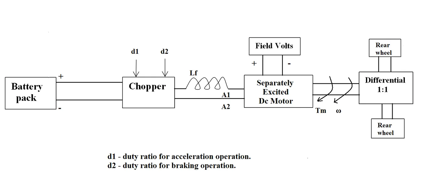
Q. 2. An Electric Vehicle's powertrain with 72V battery pack in shown in the diagram below. The duty ratio for acceleration operation is 'd1' and for the braking operation the duty ratio is 'd2'.
The other parameters of the electric vehicle is given below,
Motor and Controller Parameters:
Rated Armature voltage= 72V : Rated armature current= 400 A : Ra= 0.5Ω, KΦ= 0.7 Volt second : Chopper Switching frequency= 400 Hz
The vehicle speed-torque characteristics are given by the below equation

What is EV steady state speed if duty cycle is 70%?
ANSWER: -
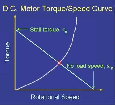
- Steady state speed of vehicle is the speed whene vehicle operate at operating point.
- Operating point for vehicle is the point where speed torque characterstics of motor and vehicle intersect,same shown in below figure.
- Vehicle can be operated at steady state point by controlling input voltage to the motor.Minimun the motor voltage operating point acheive fast.
- To control the operating point loaction or effectively as per vehicle requirenment input voltage for motor is controlled using Power controller like DC DC converters.
- DC DC controller are the type of power controller which used to step up(Boot converter) or step down(Buck converter) the voltage level in DC only.
- For operation of converter power switches like MOSFET, BJT, IGBT are used for switching,the same graph is shown in the below figure.
- The above figure shows the swtiching of the Power switches in the boost converter circuit.
- As the switch is on & off very as per their switching frequency(10kHz),according to that average voltage can be given to the motor.
- The voltage feeding to motor can be controlled by calculating DUTY CYCLE.
- DUTY CYCLE = (ON TIME) / (ON+ OFF TIME)
- Average voltage = Duty cycle * Battery voltage.
Now as per question duty cycle is 70% i.e, 0.7
hence
Average voltage (V) =0.7*72 =50.4 V
We know that motor speed torque equation is
ω= V/Kϕ -(Ra/Kϕ^2 )*Tm----------------------------------------------------------------------------(1)
and vehicle speed-torque characteristics given as
----------------------------------------------------------------------------(2)
substitute the value of Ra, V,& Kϕ In equation no 1
we get
Tm = 70.58-.98 ω
At steady state conditon motor torque and vehicle torque must be same
Tm=Tv
24.7+(0.0051)ω^2 =70.58-.98 ω
solving above quadratic equation
we get
ω=-231 & ω =39.1 as two roots of ω.
Speed must be poisitive hence we take 39.1 rad/s
To find torque steady state put above value of ω in equation no 1 or 2.
we got Tm=Tv=32.4 Nm
: ---EV steady state speed if duty cycle is 70% = 39.1 rad/sec.
----------------------------------------------------------------------------------------------------------------------------------------------------------------------------------------------------------
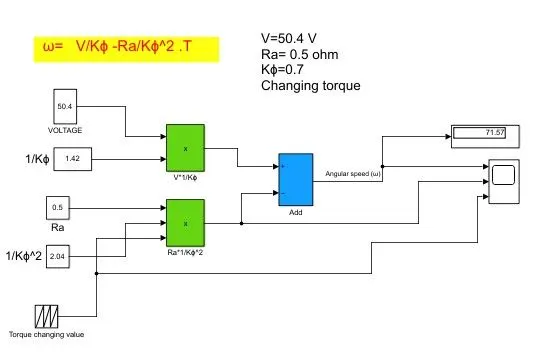
Q. 3. Develop a mathematical model of a DC Motor for the below equation using Simulink.
ω= V/Kϕ -Ra/Kϕ^2 .T
Input for the equation are V,Ra,Torque,Kϕ
Constant torque value taken in below mathematicle modelling.i,e. T =32.4Nm
We can also change the torque value.
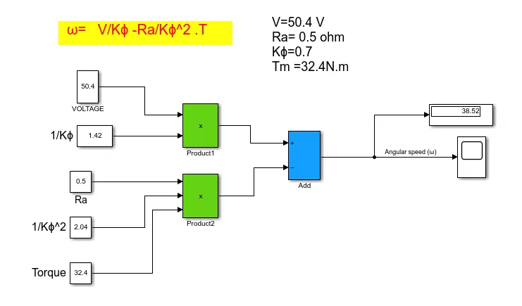
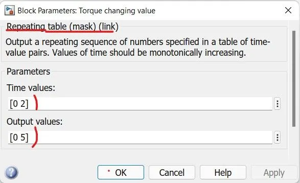
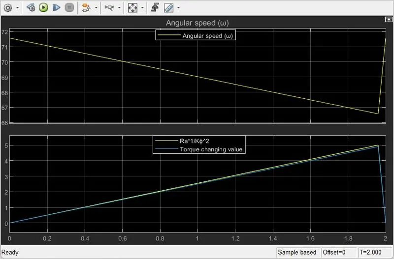
Using repeating sequence block in simulink we can cahneg value of Torque and from result we got speed and torque characterstics at steady state.
https://drive.google.com/file/d/18VOE9gqkPtFwedSe13KmdGlk495xIZA0/view?usp=sharing
Conclusion: -
- As we increase the value of torque from 0 to 5 angluar speed start decreasing from 71.5 to 67.5 rad/sec.
- Speed -torque characterstics of DC motor is obtained.
-------------------------------------------------------------------------------------------------------------------------------------------------------------------------------------------------------------------------
Q. 4. Refer to the blog on below topic:
Induction Versus DC brushless motors by Wally Rippel, Tesla
Explain in brief about author’s perspective.
ANSWER: -
Basically this blog written by Wally Rippel is about comparision of BRUSHLESS DC MOTOR & INDUCTION MOTOR.He tried to compare both the motor as per different points and give us final conclusion.
The diffrence and similarties is explained below as per sir Wally Rippel:
1. Brushless DC motor
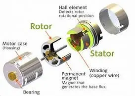
- Rotor includes two or more permanent magnets that generate a DC magnetic field.
- It is necessary that the magnitude and polarity of the stator currents be continuously varied – and in just the right way - such that the torque remains constant for that Current control is called an inverter. Without it, brushless motors are useless motors
- Brushless DC motor produces no starting torque when directly connected to fixed frequency utility power. They really need the aid of an inverter whose “phase” is maintained in step with the angular position of the rotor.
- One of the main differences is that much less rotor heat is generated with the DC brushless drive. Rotor cooling is easier and peak point efficiency is generally higher for this drive. The DC brushless drive can also operate at unity power factor.
- With DC brushless, as machine size grows, the magnetic losses increase proportionately and part load efficiency drops.
- Permanent magnets used as rotor are expensive.
- As the rotor having permanent magnet field magnetic strenght controlling is not easy.
- Efficiency for DC brushless DC motor is better as compared to IM.
2. INDUCTION MOTOR: -
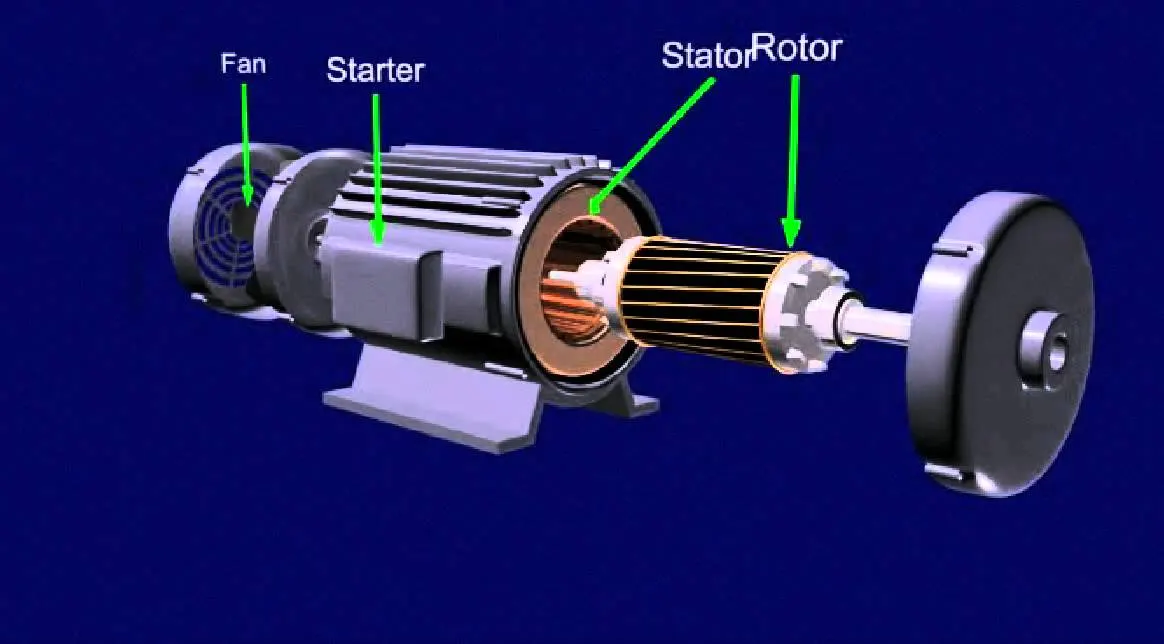
- Unlike the DC brushless rotor, the induction rotor has no magnets – just stacked steel laminations with buried peripheral conductors that form a “shorted structure.”
- No inverter is needed.
- Induction motors are directly compatible with conventional utility power is the main reason for their success.
- They can operate from DC but inverter is required to convert DC power into AC one.
- IM have limited starting torque as compare to DC brushless motor.
- Best power factor for the induction drive is about 85 percent.
- Induction motors have cost advantage over PM machines.
- Field magnetic strenght controlling is not easy.
CONCLUSION BY WALLY RIPPEL
- As per their individual characteristics both motors are good with their performance.
- Both motor generated field strength control is not easy.
- As per their characteristics Brushless DC motor can used in hybrid vehicle and in Plug in hybrid vehicle.
- Induction motor is more likely used in higher performance requiring Pure electric vehicle.