Week-6 Challenge: EV Drivetrain
1. Which types of power converter circuits are employed in electric and hybrid electric vehicle?
Power converter are semiconductor devices which either converts power(from AC to DC or Constant DC to pulsating DC) or change the level of the power by making change V or I parameters.
A power converter is an electrical circuit that changes the electric energy from one form into the desired form optimized for the specific load.
POWER CONVERTERS IN EV :
Battery charger : Consists of AC to DC converter also called rectifier
DC-DC converter or chopper : For Aux. loads
Inverter : Converts DC voltage from battery to AC for motor
AC-AC converter : AC voltage regulator
Bi-directional converter (To implement regeneration) : which allows power flow in both directions and contains AC-DC, DC-AC and DC-DC(Chopper) converter in single unit.
POWER CONVERTERS IN HEV :
There is no specific difference between the converters used in EV and HEV if purpose is taken as a context.
In HEV instead of Bi-directional converter a seperate regenerative DC-DC chopper is used to conert the mechanical energy from gasoline engine to alternator (generator) to store energy.
Types of power converters:
- AC - DC Converter (Controlled Rectifier)
- DC - DC Converter (DC Chopper)
- AC - AC Converter (AC Voltage regulator)
- DC - AC Converter (Inverter)
fig 1.1 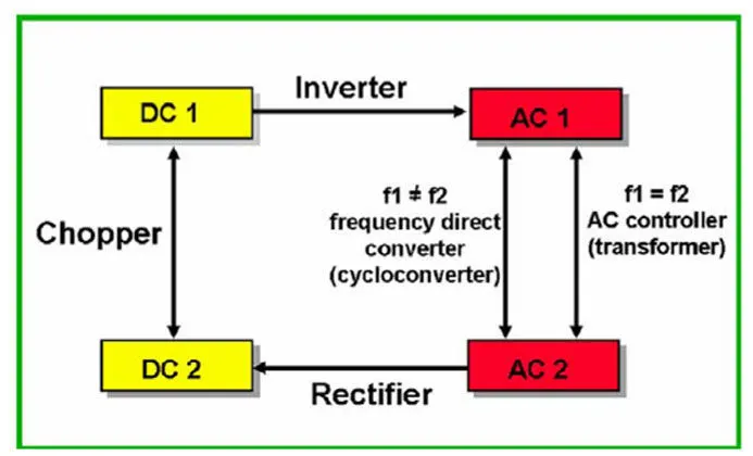
AC to DC converters :
An AC-DC converter circuit can convert AC voltage into DC voltage. The DC output voltage can be controlled by varying the firing angle of the thyristors. The AC input voltage could be a single phase or three phase.
DC to DC converters :
These converters can convert a fixed DC input voltage into variable DC voltage or vice versa. The DC output voltage is controlled by varying of duty cycle.
AC to AC converters :
This converters can convert from a fixed AC input voltage into variable AC output voltage. The output voltage is controlled by varying firing angle if TRIAC. These type converters are known as AC voltage regulator.
DC to AC converters :
This convertes can convert a fixed DC input voltage into variable AC output voltage. The output voltage is controlled by changing amplitude of Supply DC link and by changing duty cycle of control circuit. These type converters are known as inverter.
The DC to AC converters is used in a vehicle to charge their batteries. These circuits are mainly used for driving low-power AC motors and used in a solar power system.
2. EV steady state speed if duty cycle is 70% :
Data available :
Battery pack voltage(Vb) = 72 V
d1 & d2 are acceleration and braking dutycycle respectively.
Rated Armature voltage(Va) = 72 V
Rated armature current(Ia) = 400 A
Ra= 0.5 Ω
kϕ= 0.7 Volt second
Chopper Switching frequency = 400 Hz
Vehicle speed-torque characteristics equation Tv = 24.7 + 0.0051ω² ............ eq(1)
Solution :
Duty cycle = 70% = 0.7
Actual voltage = 0.7*72 = 50.4 V
Torque speed equation of DC motor , T = V.kϕ/Ra - ( (kϕ)²/Ra) ) . ω
T = V.kϕ/Ra - ( (kϕ)²/Ra) ) . ω
T = 50.4*0.7 / 0.5 - ( (0.7)²/0.5) ) . ω
T = 70.56 - 0.98ω .................eq(2)
Solving equation (1)&(2);
Comparing both torque of vehicle and torque of motor,
24.7 + (0.0051)ω² = 70.56 - (0.98)ω
0.0051ω² + 0.98ω - 45.86 = 0 ...................eq(3)
eq(3) represents the quadratic eq of form ax² + bx + c = 0
By solving eq(3) by quadratic equation we get,
ω = 38.915 rad/sec and ω = -231.072 rad/sec
So, the EV steady state speed if duty cycle is 70% = 38.915 rad/sec or 317.6 RPM
3. Mathematical model of a DC Motor for the below equation using Simulink.
ω = V/kϕ - Ra/(kϕ)².T
The simulink model of the dc motor using the equation, ω = V/kϕ - Ra/(kϕ)².T is in fig 3.1
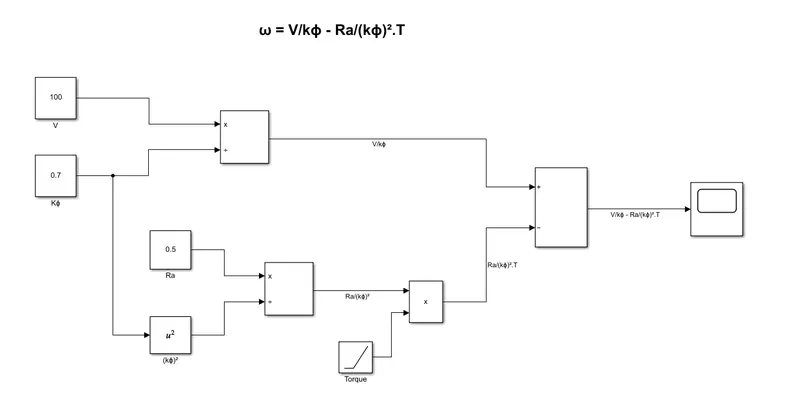 fig3.1
The above simulink model depicts the above equation ω = V/kϕ - Ra/(kϕ)².T , where a constant block is used to determine value of voltage(V) and is divide by a constat kϕ from constant. That division block output is input to the add block. Another constat block is used to take armature resistance(Ra) and is divide by (kϕ)² ( by taking square block from the path of kϕ) and is multiply with torque(T), torque is varying with time, so a ramp block is used to take torque value. These output ( V/kϕ - Ra/(kϕ)².T ) is the next input of previous mentioned add-substract block. Then the resultant output is taken into tha scope. The scope will give the solution of the equation(as in fig 3.2).
Here we take V= 100V, kϕ= 0.7 and Ra= 0.5
RESULT SCOPE :
fig 3.2 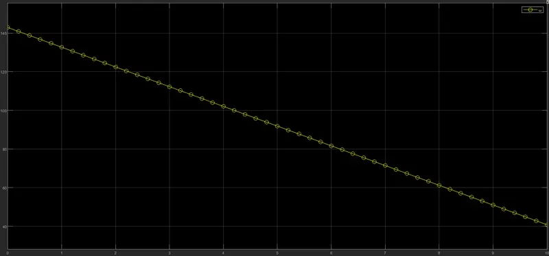
The graph shown in above depicts the result of the above equation ω = V/kϕ - Ra/(kϕ)².T , we can analyse that the speed(ω) is decreased by change the time from 0 to 10 s. and also analyse that the value ω is varied with respect to torque.
4. INDUCTION VERSUS DC BRUSHLESS MOTOR :
INDUCTION MOTOR :
An induction motor or asynchronous motor is an AC electric motor in which the electric current in the rotor needed to produce torque is obtained by electromagnetic induction from the magnetic field of the stator winding. An induction motor can therefore be made without electrical connections to the rotor.
fig 4.1 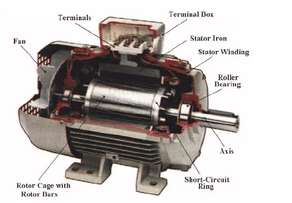
BRUSHLESS DC MOTOR :
A brushless DC electric motor, also known as electronically commutated motor or synchronous DC motor, is a synchronous motor using a direct current electric power supply.
fig 4.2 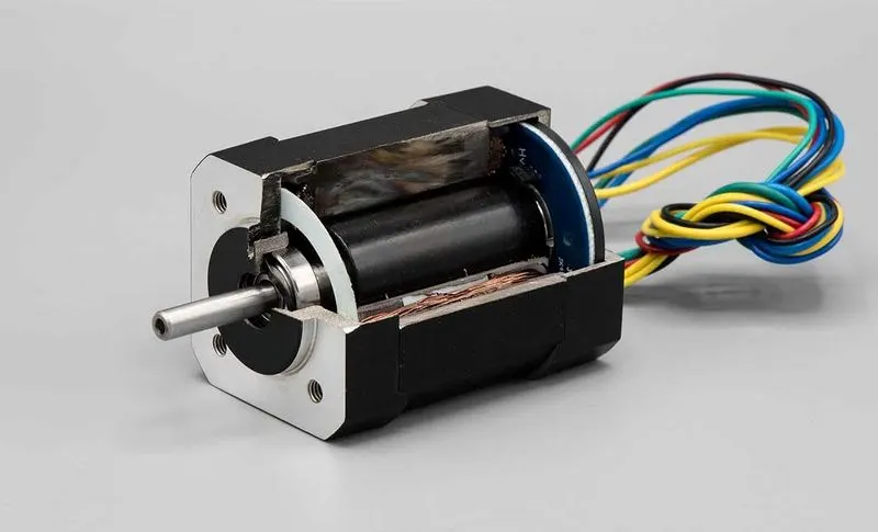
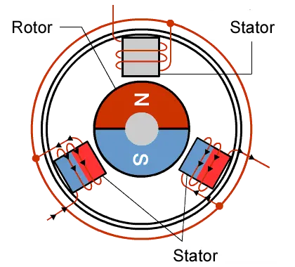 fig 4.3
According to the authors perspective,
- Fistly he gave the discription of DC brushless motor about its parts and specifications and next description about induction motor about is component and working of induction motor. Then he compared the DC brushless and induction motor. He mentioned that 3-phase induction motor can produce output torque and also have an ability to start under the load without any inverter, as of brushless DC motor produces no starting torque when directly connected to fixed frequency utility power and also inverter is needed to start under load.
- Then he discussed about the limitation of the 3-phase induction motor they cannot operate from DC, AC is must needed. Shaft speed is proportionate to line frequency. When used with utility power, they are constant speed machines. finally when operated from utility power, they have limited starting torque and some what limited running peak torque capabilities, when compared to DC type machines. Inverter can be added to 3-phase induction so that we can supply power from DC source or battery and aslo we can get variable speeds and can adjust the frequencies.
- Then he discussed about the main difference between DC brushless and indution motor is of control code and the rotor of DC brushless gets less heated at peak torque compared to induction motor rotor.
- Then he discussed about the losses when the motor runs which is the induction machine when operated with a smart inverter has an advantage over a DC brushless machine, magnetic and conduction losses can be traded such that efficiency is optimized. This advantage becomes increasingly important as performance is increased.
- With DC brushless, as machine size grows, the magnetic losses increase proportionately and part load efficiency drops. with induction motor, as machine size grows, losses do not necessarilygrow. Thus induction may be the favored approach where high-performance is desired. peak efficiency will be a little less than with DC brushless, but average efficiency may actually be better.
- Last he concluded with that DC brushless drives will likely continue to dominate in the hybrid and coming plug-in hybrid markets, and that induction drives will likely maintain dominance for the high-performance pure electrics.