Week-6 Challenge: EV Drivetrain
EV BATCH - 17
1 . Which types of power converter circuits are employed in electric and hybrid electric vehicle
ANS :
ELECTRIC VECHICLE :
- An electric vehicle (EV) is a vehicle that uses one or more electric motors or traction motors for propulsion.
- An electric vehicle may be powered through a collector system by electricity from off-vehicle sources, or may be self-contained with a battery, solar panels, fuel cells or an electric generator to convert fuel to electricity.
HYBRID ELECTRIC VECHICLE :
- A hybrid electric vehicle (HEV) is a type of hybrid vehicles that combines a conventional internal combustion engine (ICE) system with an electric propulsion system.
- The presence of the electric powertrain is intended to achieve either botter fuel economy than a conventional vehicle or better performance.
- There is a variety of HEV types and the degree to which each function as an electric vehicle (EV) also varies.
- The most common form of HEV is the hybrid electric car, although hybrid electric trucks (pickups and tractors), buses boats and aircraft also exist .
POWER CONVERTOR CIRCUITS FOR ELECTRIC AND HYBRID ELECTRIC VECHICLE :
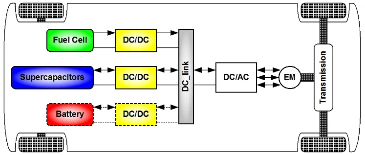 The different configurations of EV power supply show that at least one DC/DC converter is necessary to interface the FC, the Battery or the Supercapacitors module to the DC-link DC/DC converters can be designed to transfer power in only one direction from the input to the output. However, almost all DC/DC converter topologies can be made bi directional A bi-directional converter can move power in either direction, which is useful in applications requiring regenerative broking The most comman DC/DC converters can be grouped as follows:
Non-isolated converters :
- The non isolated converters type is generally used where the voltage nouds to be stopped up or down by a relatively small ratio (less than 41).
- And when there is no problem with the output and input having no dielectric isolation There are five main types of converter in this non-isolated group usually called the buck boost buck boost.
- Cuk and charge-pump converters. The buck converter is used for voltage step down whille the boost converter is used for voltage step up.
- The buck boost and Cuk converters con no used for either step-down or step-up.
- The charge pump converter is used for either voltage step-up or voltage inversion but only in relatively low power applications
Isolated converters :
- Usually, in this type of converters a nigh frequency transformer is used in the applications anere the output needs to be completely isolated from the input an isolated converter is necessary.
- There are many types of converters in this group such as Hofferage Full-Bnage My back, forware and Puen-Fall BC/DC ponverters All of these be used as bi-directional converters and the ratio of stopping down or stepping up the voltage is high .
Non-isolated converters :
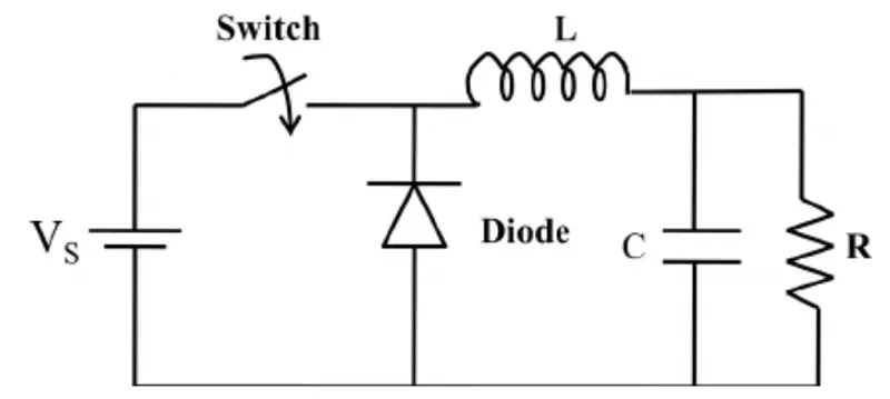
Buck :
- A buck converter (step-down convined) is a DC to DC power convertor which steps down voltage from s input(supply) tons output (load) it is a class of switched moge power supply [SMP Typicary containing at least two semiconductors a diode and a transistor, atuough modern buck.converters frequently replace ine diode with a second transistor used for synchronous rectification and at least one energy storage elament, o capacitor inductor or the two in combination.
- To reduce voltage ripp Tillers mod of capacitors (offers in combination with inductors are normally paded to such a convertel's output lood-sids filter) and imput (supply-sido filter)
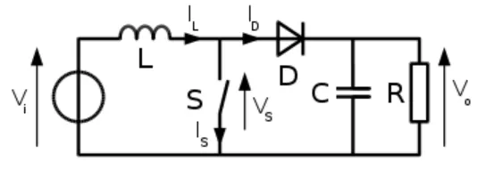
BOOST :
- A boost converter (step-up converter) is a DC to DC converter that steps up voltage from its input (supply) to its output (load).
- It is a class of switched mode power supply (SMPS) containing at least two semiconductors a diode and a transistor and at least one energy storage element: a capacitor inductor or the two in combination. To reduce voltage ripple, filters made of capacitors (sometimes in combination with inductors) are normally added to such a converter's output (load-side filter) and input (supply-side filter).
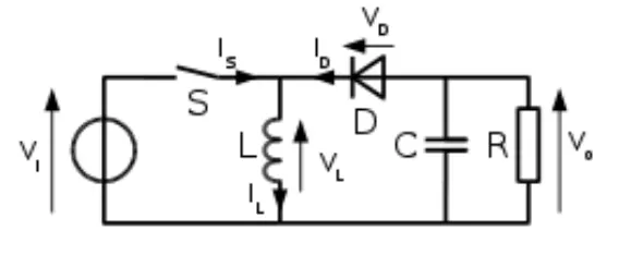
BUCK-BOOST :
- Buck-boost- The buck-boost converter is a type of DC to DC converter that has an output voltage magnitude that is either greater than or less than the input voltage magnitude. It is equivalent to a llyback converter using a single inductor instead of a transformer.
CUK :
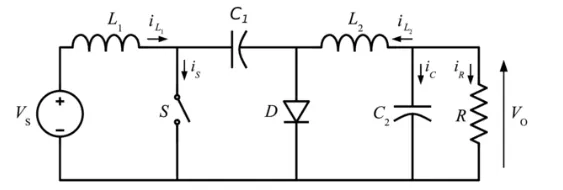
- The Cuk converter is a type of buck-boost converter with zero ripple current. Cuk converter can be seen as a combination of boost converter and buck-converter, having one switching device and a mutual capacitor, to couple the energy.
charge-pump :
- A charge pump is a kind of DC to DC converter that uses capacitors for energetic charge storage to raise or lower voltage. Charge-pump circuits are capable of high efficiences, sometimes as high as 90-95%, while being electrically simple circuits Isolated converters:
Half bridge :
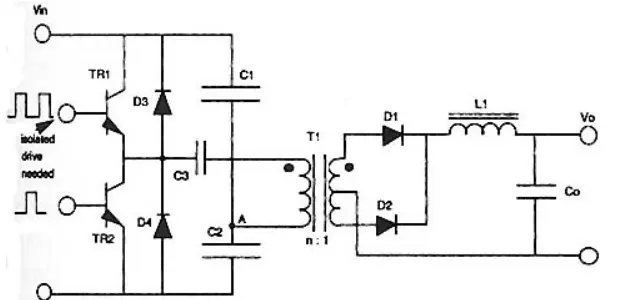
- A half-bridge converter is a type of DC-DC converter that, like flyback and forward converters, can supply an output voltage either higher or lower than the input voltage and provide electrical isolation via a transformer.
Full bridge :
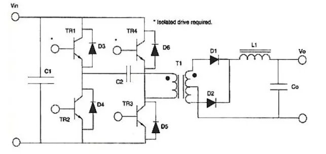
- The full-bridge converter adds two additional transistors to the half-bridge converter.
- This means that four transistors are available to provide power to the output section, so this type of converter is used in power supplies in excess of 1000 Watts.
- Fig. shows the schematic of the full-bridge converter.
- Each transistor has a clamping diode connected across its collector-emitter terminals and they are driven alternately in pairs.
- Transistors TI and T3 are energized together for one half-cycle, and transistors T2 and T4 are energized together for the other half-cycle.
- One advantage of the full-bridge converter is that it only requires one capacitor for smoothing the output voltage, whereas the half-bridge converter required two.
- The full-bridge converter will be used in larger power supplies usually over 1000 Watts.
- Since this type of converter is more complex, it's normally used in the largest types of power supplies.
Push pull :
- As the switch-mode power supply has evolved, additional adjustments to the original circuits have been made to get more power from smaller components.
- This means that the efficiency for the system must be increased.
- One simple way to do this is to use a center-tapped transformer that utilizes both the top and bottom half cycles.
- Fig. shows a schematic of the push-pull converter in which the push-pull converter utilizes a center-tapped transformer for both the primary and secondary windings.
- The primary winding is controlled by two transistors, which allow one of them to conduct during each half cycle, so the output is receiving voltage directly through one of them at all times.
- This means that the efficiency of this configuration is approximately 90%. This allows the overall size for the power supply to be smaller for a comparable power supply whose efficiency is 75% to 80% .
.......................................................................................................................................................................................................................................................................................................
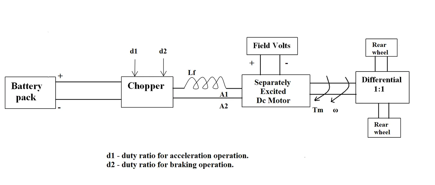
2 . An Electric Vehicle's powertrain with 72V battery pack in shown in the diagram below. The duty ratio for acceleration operation is 'd1' and for the braking operation the duty ratio is 'd2'.
The other parameters of the electric vehicle is given below,
Motor and Controller Parameters:
Rated Armature voltage= 72 V
Rated armature current= 400 A
Ra= 0.5Ω, KΦ= 0.7 Volt second
Chopper Switching frequency= 400 Hz
The vehicle speed-torque characteristics are given by the below equation

What is EV steady state speed if duty cycle is 70%?
GIVEN DATA :
The following input parameters are given :
Battery Pack voltage(V) = 72 V
Rated armature current = 400 A
Armature Resistance (Ra) = 0.5
Motor Constant (K) = 0.7
Chopper Switching frequency = 400 Hz
Duty Cycle 70%
Solution:
Vehicle Output Voltage = Battery Voltage(V)+Duty Cycle
=72 0.70
= 50.4 V
So, the vehicle voltage is 50.4 V Now,
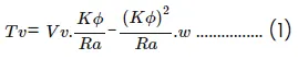
Equation for Vehicle torque is :
Where,
Tv= Vehicle Torque (N-mm) V=Vehicle Voltage (Volts)
 = Steady State speed of Vehicle (rps)
KΦ = Motor Constant
Ra = Armature Resistance
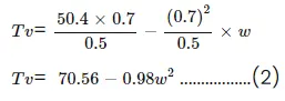
Substituting all the values in equation 1, we got
Now, the vehicle speed torque characteristics is given as ,

At steady state ,
Eq (2) = Eq (3) ..............(4)
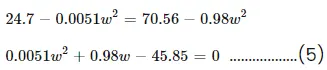
To solve the above Eq we have to apply the QUADRANT EQUATION
FORMULA :
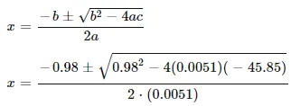
= 38.92 rad/sec
So, The steady - state speed of the vehicle is 38.92 rad/sec .
.........................................................................................................................................................................................................................................................................................................
3 . Develop a mathematical model of a DC Motor for the below equation using Simulink.
ω= V/Kϕ-Ra/Kϕ^2 .T
AIM :
To Develop a mathematical model of a DC Motor for the below equation using Simulink.
ω= V/Kϕ-Ra/Kϕ^2 .T
DC MOTOR :
- A DC motor is any of a class of rotary electrical motors that converts direct current (DC) electrical energy into mechanical energy.
- The most common types rely on the forces produced by magnetic fields. Nearly all types of DC motors have some internal mechanism, either electromechanical or electronic, to periodically change the direction of current in part of the motor.
- DC motors were the first form of motor widely used, as they could be powered from existing direct-current lighting power distribution systems.
- A DC motor's speed can be controlled over a wide range, using either a variable supply voltage or by changing the strength of current in its field windings.
- Small DC motors are used in tools, toys, and appliances.
- The universal motor can operate on direct current but is a lightweight brushed motor used for portable power tools and appliances.
- Larger DC motors are currently used in propulsion of electric vehicles, elevator and hoists, and in drives for steel rolling mills.
- The advent of power electronics has made replacement of DC motors with AC motors possible in many applications.
SIMULATION BLOCKS :
- CONSTANT BLOCK
- RAMP BLOCK
- PRODUCT BLOCK
- SQUARE BLOCK
- ADD BLOCK
- SCOPE
SIMULATION MODEL :
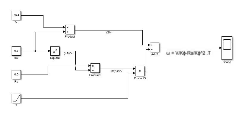
EXPLANATION :
- First open the matlab and click on the simulink then we get simulink blank model .
- Next go to the library and search the required blocks i.e, constant, ramp, product , add, scope, square .
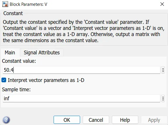
- Now change the constant value is 50.4 v let consider this constant as voltage .
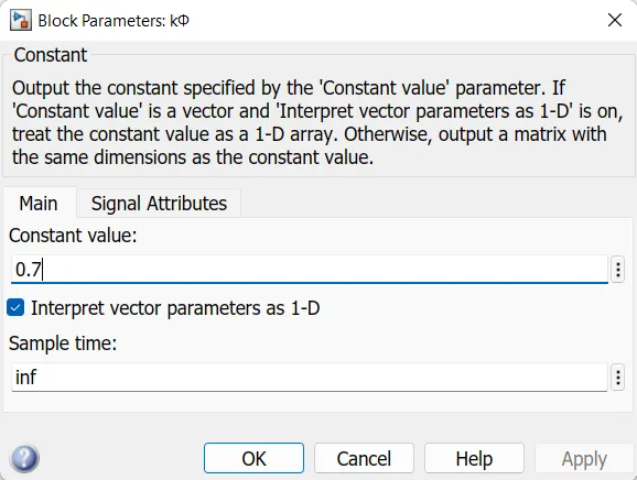
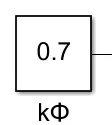
- Then change value of another constant is 0.7 let consider this constant as kϕ.
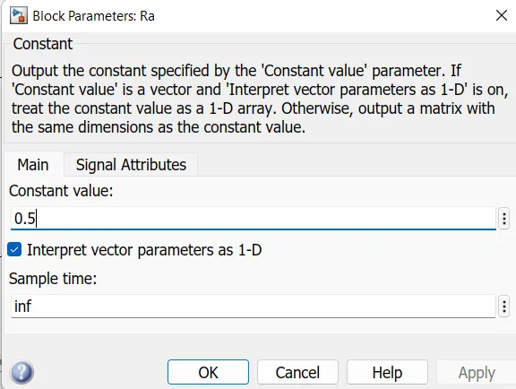
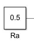
- Now change the value of another constant is 0.5 let this constant consider as Ra.
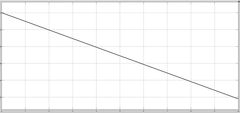
- connect the circuit as per the above figure . Now click on the run button after complete the compile we can check the results in the scope .
OUTPUT :
CONCLUSION :
The mathematical model of a DC motor by using given equation ω= V/Kϕ-Ra/Kϕ^2 .T is done .
.......................................................................................................................................................................................................................................................................................................
4 . Refer to the blog on below topic:
Induction Versus DC brushless motors by Wally Rippel, Tesla
Explain in brief about author’s perspective.
ANS :
EXPLAINATION IN AUTHOR'S PERSPECTIVE :
- The author writes this blog to entail the differences between the two most commonly used motor drives in the automobile industry: the DC brushless motor drive and the induction motor drive.
- Rippel goes in to detail about the differences in construction, working, and cost between the two drive types.
- However, with what he has written, he has not arrived at the conclusion that one type is better than the other.
- In the last lines of the opening paragraph, Rippel writes that there is no one best engine type" and that it is all a matter of personal preference when it comes to choosing an engine.
- It is in this same regard that he ends the blog stating that there is still 'no winner when it comes to motor drive selection either.
- In spite of both motor drive types having similarities, they also have their benefits and drawbacks.
- For DC Brushless drives, we are told that their construction implements 2 or more permanent magnets at the rotor to generate a DC magnetic field.
- It also consists of a stator core (made up of thin, stacked laminations) It also uses an inverter for the current control, meaning that it cannot run on a DC power supply as the current direction has to be changed repeatedly in to maintain a constant torque.
- For induction drives, there rotor has no magnets, but instead stacked steel laminations with buried peripheral conductors which form a shorted structure. It is the current in the stator windings that generates a rotating magnetic field that interacts with the rotor.
- Induction motors can be used directly with power from the mains and does not require an inverter to start the drive and generate the starting torque.
- It has the ability to start under the mains load applied However, DC brushless drives cannot do the same.
- They cannot generate a starting torque when connected to a mains power supply They require an inverter to do this.
- Induction motor drives cannot run on a DC power supply and are solely dependent on an AC power supply.
- Also, when they are connected to a 3 phase moins supply, the rotor rotates at a constant speed and also they have a limited starting torque as well as peak torque.
- In order to rectify this, an inverter can be used to operate the induction drive from a DC power supply or a battery.
- Also, if the inverter frequency is varied, then the constant speed is no longer an issue it can be varied.
- DC Brushless drives use permanent magnets, and cannot change the strength of their magnetic fields.
- It would be desirable if they could, because when the maximum torque is needed by the rotor, the magnetic field strength should also be at a maximum level.
- This allows for the inverter and motor currents to be at a minimum, thereby reducing the power loss by heat dissipation Similarly, when the torque required is minimum, the magnetic field strength should also be minimum to reduce hysteresis and eddy current losses.
- The permanent magnets used are also quite expensive costing $50 per kilogram and their magnetic fields are difficult to control if ferromagnetic material gets close enough to the field.
- On the other hand, induction drives do not have permanent magnets and so they can vary their magnetic field strength If used with a smart inverter, they can be operated with minimum hysteresis and eddy current losses and maximum efficiency as the magnetic field strength can be changed according to the requirement by the rotor.
- These osses do not increase if the size of the Induction drive also increases but as a DC brushless drive gets bigger, its losses increase and their officiency decreases. So induction drives have a cost advantage compared to DC brushless drives.
- Although, DC Brushless drives generate less heat at the rotors.
- So rotors more easily and have a higher peak point efficiency than induction drives.
- In addition, the DC brushless motor can operate at unity power factor i.e. 1, whereas induction drives can operate up to a power factor of approximately 85%.
- In conclusion, Rippel has elaborated the different aspects to compare the induction and DC brushless motor drives and has detailed the advantages and disadvantages of both types.
- As mentioned earlier, at the end of the day it depends on the preference of the user.
- If a user is seeking a high performance with comparatively lesser costs, then the induction drive would be better suited for those requirements.
- However, if it is high peak point efficiency, high power factor and easier control that a user seeks, then the DC brushless drive would be the smarter choice. Both types have their place in the automobile industry and will retain their relevance in their respective applications.
- Rippel believes that due to the increasing performance of vehicles, one day both may be used side by side under the hood of a vehicle in order to get the best of both drives.
- This would result in a new kind of hybrid that combines the characteristics of an ordinary vehicle e.g. sedan with that of a sports car.
.......................................................................................................................................................................................................................................................................................................