Week -2
EV BATCH - 17
1. Make a Simulink model of Doorbell using solenoid block
AIM : To make a Simulink model of Doorbell using solenoid block with the fgiven condition :
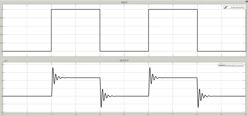
Create a situation where the switch is closed for 2 seconds and then released.
BLOCKES USED :
- Pulse generator
- Simulink ps converter
- Ps switch
- Battery
- Solenoid
- Electrical reference
- Ideal translation motion sensor
- Mechanical translation reference
- Ps simulink converter
- Solver configuration
- Display
- Scope
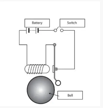
Circuit diagram :
SIMULATION DIAGRAM :
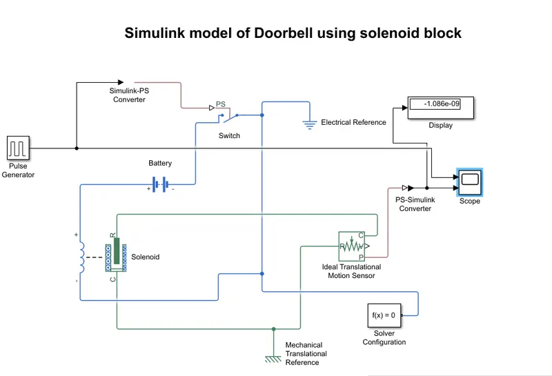
EXPLANATION :
- First we have to open the matlab and click on the simulink and then we get the simulink blank model.
- Now click on the library and search the blockes we want i.e pulse generator, simulink ps converter, ps switch, battery, solenoid, electrical reference, ideal translational motion sensor, solver configuration, ps simulink conveter, mechanical translational reference, display and scope.
- Connect the pulse generator to the input of ps converter and the ouput of ps converter is connected to the ps switch.
- Negitive terminal of battery is connected to the switch and positive terminal of battery is connected to the positive teminal of soleniod and then negitive terminal of solenoid is connected to the switch.
- Next R terminal of soleniod is connected to the C terminal of ideal sensor and C terminal of soleniod is connected to the R terminal of sensor .
- Next P terminal of the sensor is connected to the input of ps simulink conveter and output of ps simulink conveter is connected to the scope and display.
- Electrical reference, solver configuration, mechanical translational reference is connected t the circuit as shown in the figure aboe.
- The pulse generator is used to give the signal input where, Amplitude=1, Period=4 sec, Pulse width= 50%, and phase dilay = 2 sec.
- Here the simulink ps converter is used to convert the input signal into physical form to give the the ps switch .
- And ps simulink converter is used to convert the physical form to output signal .
- Solver configuration is used to solve the all paramaters in the circuit before the simulation ans scope and display is used to chech the results.
Result :
...................................................................
2. Use a thermistor to sense the temperature of a heater & turn on or turn off the fan
AIM : TO Use a thermistor to sense the temperature of a heater & turn on or turn off the fan
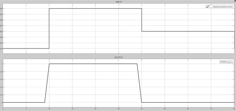
Temperature source: 20 °C from 0 to 10 seconds, 27 °C from 10 to 30 seconds, 23 °C from 30 to 50 seconds
Fan conditions: ON if the temperature above 25 °C, OFF otherwise.
BLOCKES USED :
- Repeating sequence stair
- Simulink ps converter
- Solver configuration
- Controlled temperature source
- Thermal reference
- Thermistor
- Voltage sensor
- Resistor
- Battery
- Electrical reference
- ps simulink converter
- constant
- switch
- scope
SIMULATION DIAGRAM :
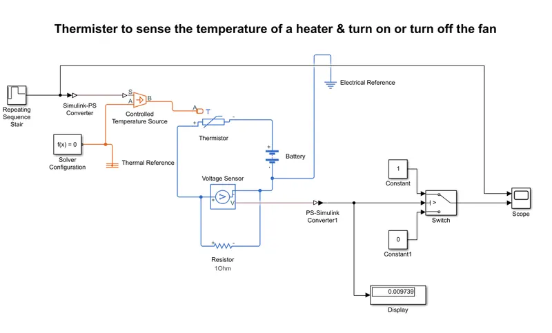
EXPLANATION :
- First we have to open the matlab and click on the simulink and we get the simulink balnk model.
- Click on the library and search the required blockes i.e., Repeating sequence stair, Simulink ps converter, Solver configuration , Controlled temperature source, Thermal reference, Thermistor, Voltage sensor, Resistor, Battery, Electrical reference, ps simulink converter, constant, switch, scope.
- Now repeating sequence stair is connected to the input of simulink ps converter and output is connected to the S terminal of controlled temperature source.
- Solver conguration and thermal reference is connected to the A terminal of the controlled temperature source.
- And B terminal of controlled temperature source is connected to the A terminal of thermister. Negitive terminal of thermister is connected to the positive terminal of battery .
- Positive terminal of thermister is connected to the positive terminal of the voltage sensor and negitive terminal of sensor is connected to negitive terminal of battery. Resisstor is connected to the voltage sensor in parallel.
- Next V terminal of sensor is connected to the input of ps simulink converter and output of the converter is connected to both display and V terminal of switch.
- output of the switch is connected to the scope and constant is coneected to the switch . electrical reference is connected to battery as shown in above figure.
- Here the singnal is passes through the switch where a threshold limit is already set.
- If the temperature is above or equal to the threshold limit, then it gives output is high or "1" which means the switch is ON condition.
- If the temperature is below the threshold limit, then it gives the output is low or "0" which means the switch OFF condition .
- Here the value of threshold limit is 0.0116. Here the temperature is converted in Kelvin from degree Celcius because the signal converter does not take °C value as input. I also have to set the signal unit as "Kelvin" in Simulink-PS Converter. The formula for conversion: 1°C= 273.15 K.
- Change the stop time as 50 sec before run the simulation .After change the stop time run the simulation and check the results in the scop.
RESULTS :