Week-6 Challenge: EV Drivetrain
# AIM
1) Types of power converter circuits employed in an electric and hybrid electric vehicle.
2) To find the EV steady-state speed if the duty cycle is 70%.
3) Develop a mathematical model of a DC Motor.
4) Refer to the blog and explain in brief about the author’s perspective.
# OBJECTIVE
1) Briefly explain about the types of power converter circuits employed in an electric and hybrid electric vehicle.
2) To find the EV steady-state speed if the duty cycle is 70%.The vehicle speed-torque characteristics are given by the below equation

3) Develop a mathematical model of a DC Motor for the below equation using Simulink.
ω= V/Kϕ -Ra/Kϕ^2.T
4) Refer to the blog and explain in brief about the author’s perspective.
# THEORY
1)Types of power converter circuits employed in an electric and hybrid electric vehicle
The large number of automobiles in use around the world has caused and continues to cause serious problems to the environment and human life. Air pollution, global warming, and the rapid depletion of the earth’s petroleum resources are now serious problems.
Electric Vehicles (EVs), Hybrid Electric Vehicles (HEVs), and Fuel Cell Electric Vehicles (FCEVs) have been typically proposed to replace conventional vehicles in the near future. An Electric Vehicle is a vehicle that uses a combination of different energy sources, Fuel Cells (FCs), Batteries, and Supercapacitors (SCs) to power an electric drive system. In EV the main energy source is assisted by one or more energy storage devices. Thereby the system cost, mass, and volume can be decreased, and a significantly better performance can be obtained. Two often-used energy storage devices are batteries and SCS. They can be connected to the fuel cell stack in many ways. A simple configuration is to directly connect two devices in parallel, (FC/battery, FC/SC, or battery/SC). However, in this way, the power drawn from each device cannot be controlled but is passively determined by the impedance of the devices. The impedance depends on many parameters, e.g. temperature, state of charge, health, and point of operation. Each device might therefore be operated in an inappropriate condition, e.g. health and efficiency. The voltage characteristics also have to match perfectly of the two devices, and only a fraction of the range of operation of the devices can be utilized, e.g.In fuel cell battery configuration the fuel cell must provides almost the same power all the time due to the fixed voltage of the battery, and in a battery or supercapacitor configuration, only a fraction of energy exchange capability of the supercapacitor can be used. This is again due to the nearly constant voltage of the battery. By introducing DC/DC converters one can choose the voltage variation of the devices and the power of each device can be controlled.
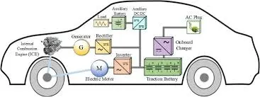
On electric vehicles (EVs), which include both fuel cell electric vehicles (FCVs) and battery electric vehicles (BEVs), and hybrid electric vehicles (HEVs) the converter, inverter, and controller are integrated into one unit, but each performs different tasks. These electronics generate a lot of heat and have their own dedicated cooling system separate from the engine which includes its own pump and radiator.
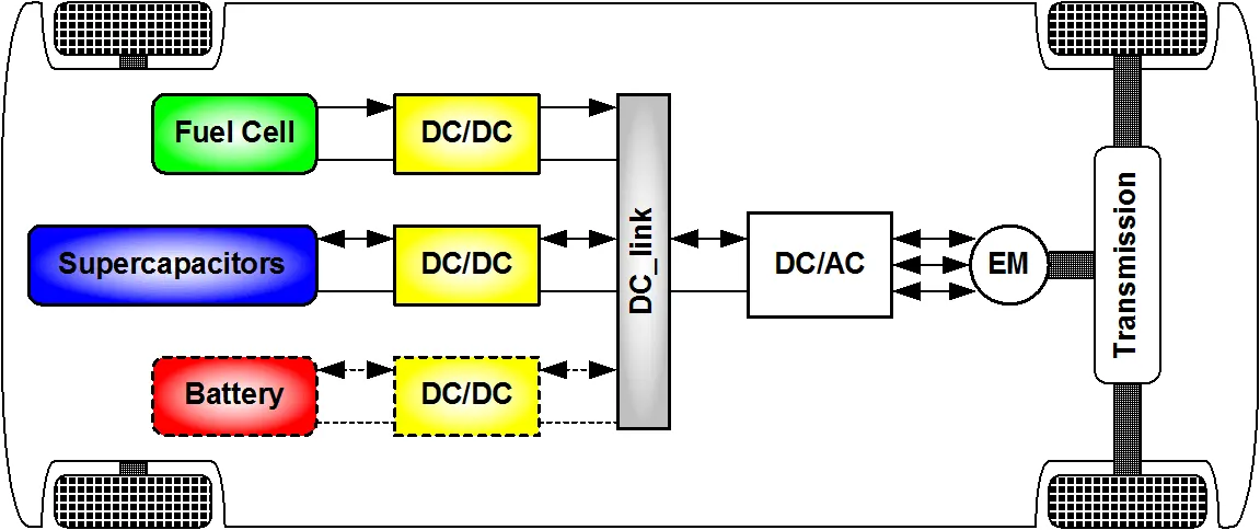
Fig 1: Electric vehicle
*AC TO DC Converter(Rectifiers)
AC to DC Converters are one of the most important in power electronics because there are a lot of real applications are based on these conversions. The AC current to dc current conversion process is known as rectification. This rectifier converts the AC supply into the DC supply at the load end connection. Normally Transformers are used to adjust the AC source to get a step-down transformer to reduce the voltage level to have a better operation range for DC supply. Normally this AC to DC converter converts low voltage values.
Uncontrolled converter converts fixed DC voltage, which means the value of output for a given value of AC voltage. A fully controlled converter converts adjustable DC voltage when the adjustable range can adjust on both the positive and negative sides. Semi-controlled converter also produces an adjustable DC voltage which has positive side power.
All three converters have unidirectional power flow from the AC side to the DC side. PWN converter can produce adjustable both positive importantly it allows power flow in either direction. Making it an ideal application for motor drives and power system interconnection with the power system.
All three converters have unidirectional power flow from the AC side to the DC side. PWN converter can produce adjustable both positive importantly it allows power flow in either direction. Uncontrolled rectifiers can also subdivide into several subcategories such as
- Single-phase half-wave rectifier. Single-phase half-wave rectifier simplest controlled rectifier uses for single devices. To produce variable de voltage from fixed current thyristors are used. Following are the circuit arrangement of the Single-phase half-wave rectifiers. In here diode or thyristors are used. Where the application needs to fix dc Voltage, the diode is used as a switching element. When the application needs variable voltage thyristors are used.
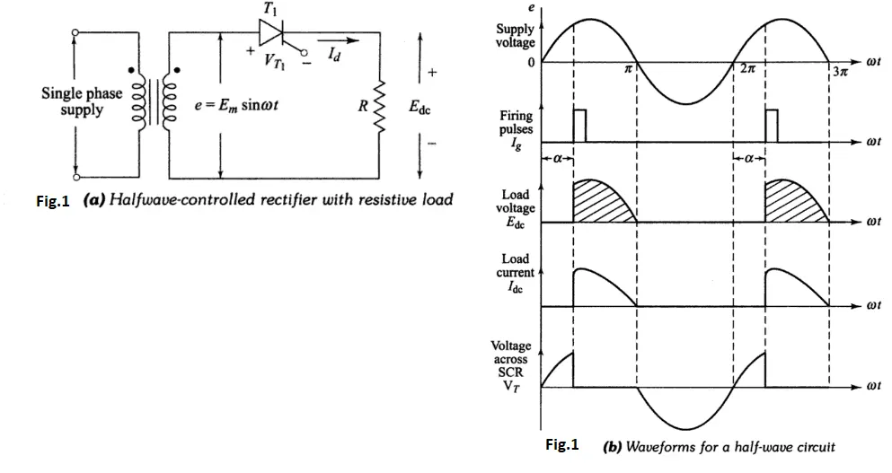
Fig 2: Single-phase half-wave rectifier
- Single-phase full-wave bridge rectifier
Another type of circuit that produces the same output waveform as the full-wave rectifier circuit above, is that of the Full Wave Bridge Rectifier. This type of single-phase rectifier uses four individual rectifying diodes connected in a closed-loop “bridge” configuration to produce the desired output. The main advantage of this bridge circuit is that it does not require a special center-tapped transformer, thereby reducing its size and cost. The single secondary winding is connected to one side of the diode bridge network and the load to the other side
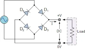
Fig 3: Single-phase full-wave bridge rectifier
- Single-phase center tapped full wave
We have already discussed the Full Wave Bridge Rectifier, which uses four diodes, arranged as a bridge, to convert the input alternating current (AC) in both half-cycles to direct current (DC). In the case of a center-tap full-wave rectifier, only two diodes are used and are connected to the opposite ends of a center-tapped secondary transformer as shown in the figure below. The center tap is usually considered as the ground point or the zero voltage reference point
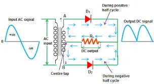
Fig 4: Single-phase center tapped full wave
- Three phases half-wave diode rectifier
The advantage here is that a three-phase alternating current (AC) supply can be used to provide electrical power directly to balanced loads and rectifiers. Since a 3-phase supply has a fixed voltage and frequency it can be used by a rectification circuit to produce a fixed voltage DC power which can then be filtered resulting in an output DC voltage with less ripple compared to a single-phase rectifying circuit.
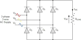
Fig 5: Three phases half-wave diode rectifier
*DC TO AC Converter(Inverters)
An inverter is a device that converts DC power from the battery to AC power used in an electric vehicle motor. The inverter can change the speed at which the motor rotates by adjusting the frequency of the alternating current. The use of Inverters can increase or decrease the power or torque of the Engine the motor by adjusting the amplitude of the signal. It plays a significant role in capturing energy from regenerative braking and feeding it back to the battery. The output voltage waveform of ideal inverters should be sinusoidal, However, the waveform of practical inverters are non-sinusoidal and contain certain harmonics. The inverter in an EV is also what's called a VFD – Variable Frequency Drive. The sine wave AC power can be generated in a wide range of different frequencies.The inverter outputs a pulsed voltage, and the pulses are smoothed by the motor coil so that a sine wave current flows to the motor to control the speed and torque of the motor. The voltage output from the inverter is in pulse form. The pulses are smoothed by the motor coil, and a sine wave current flows.
The main function of this kind of inverter is to change the input of DC to the output of three-phase AC. A basic 3-phase inverter includes 3 single-phase inverter switches where each switch can be connected to one of the 3 load terminals. Generally, the three arms of this inverter will be delayed with 120 degrees angle to generate a 3-phase AC supply. The switches used in the inverter have 50% of ratio and switching can be occurred after every 60 degrees angle. The switches like S1, S2, S3, S4, S5, and S6 will complement each other. In this, three inverters with single-phase are placed across a similar DC source. The pole voltages within the three-phase inverter are equivalent to the pole voltages within the half-bridge inverter with a single-phase.’The two types like the single-phase and three-phase include two conduction modes like 180 degrees conduction mode and 120 degrees conduction mode.
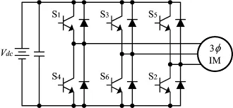
Fig 6: DC TO AC Converter
*DC TO DC Converter (Choppers)
DC-DC converters in an electric vehicle may be classified into unidirectional and bidirectional converters Unidirectional DC-DC converters cater to various onboard loads such as sensors, controls, entertainment, utility, and safety equipment. They are also used in DC motor drives and electric traction. Bidirectional DC-DC converters find applications in places where battery charging, regenerative braking, and backup power are required. The power flow in a bidirectional converter is usually from a low voltage end such as a battery or a supercapacitor to a high voltage side and is referred to as boost operation.
During regenerative braking, power flows back to the low voltage bus to recharge the battery (buck mode). As a backup power system. the bidirectional DC-DC converter facilitates the safe operation of the vehicle when ICES or electric drives fail to drive the motor. Due to the aforementioned reasons, high power bidirectional DC-DC converters have gained a lot of importance in the recent past
The converter topologies are classified as
Buck ConvertersA buck or step-down converter is a DC/DC switch-mode power supply that is intended to buck (or lower) the input voltage of an unregulated DC supply to a stabilized lower output voltage. Buck converters are, especially compared to traditional voltage regulators, widely valued for their extremely high efficiencies which can easily exceed 95%. The below-simplified circuit diagram shows how current flows through the circuit during a switching event of a buck converter. 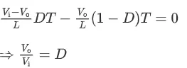
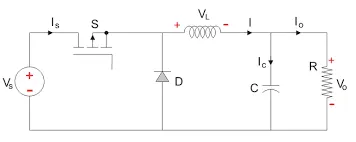
Fig 7: Buck Converter
- Boost ConvertersA boost converter is a DC/DC switch-mode power supply that is intended to boost (or increase) the input voltage of an unregulated DC supply to a stabilized higher output voltage. Similar to a buck converter, a boost converter relies on an inductor, diode, capacitor, and power switch to regulate the output voltage, but they are arranged differently.
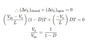
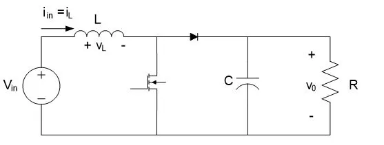
Fig 8: Boost Converter
- Buck-boost ConvertersA buck-boost boost converter can supply a regulated DC output from a power source delivering a voltage either below or above the regulated output voltage. A buck-boost converter circuit combines elements of both a buck converter and a boost converter, however, they are often larger in footprint than either alternative. The below-simplified circuit diagram shows a typical flow of current during a switching event through a buck-boost converter.
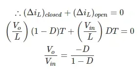
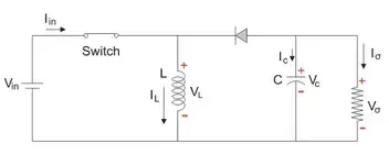
Fig 9: Buck Boost Converter
2) EV steady-state speed
vehicle output voltage (Vv)
Vv=Battery voltage (V)*Duty cycle
V=Vv=72*0.70
Thus vehicle voltage =50.04
Now Equation for vehicle torque is given by
Tv= VvKϕ/Ra -(Kϕ^2/Ra)*ω
Tv= Vehicle Torque (N-m)
Vv=50.04V= Vehicle voltage (Volts)
ω =steady-state speed of the vehicle (rps)
Kϕ=0.7 volt second=Motor constant
Ra=0.5Ω=Armature Resistance
Substituting all these values in the equation, we get:
Tv=(50.04* 0.7)/0.5-(0.7^2/0.5)* ω
Tv= 70.56 - 0.98ω
Tv= 24.7 + 0.0051ω^2
Solving these two equations
70.56 - 0.98ω = 24.7 + 0.0051ω^2
We get a quadratic equation
0.0051ω^2+0.98ω-46.94=0
since the quadratic equation, we get two values
ω=38.85 rad/s and -230.95 rad/s
we have taken positive value,
Steady-state speed of the vehicle=38.85 rad/s
3) Develop a mathematical model of a DC Motor
ω= V/Kϕ -Ra/Kϕ^2.T
let
V=50.4 volts
Kϕ=0.7
Ra=0.5 ohms
let us consider torque as a linearly increasing signaled that is equal to the ramp block of the following Simulink model
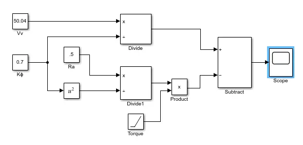
Fig 10 : Mathematical Model of a DC motor
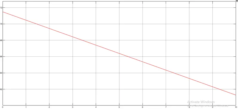
Fig 11 : Speed Curve of DC motor
- Torque of DC motor is proportional to magnetic flux
- But speed is inversely proportional to the flux.
- As the armature current increases, the flux also increases, but the speed decreases.
- The speed of the motor is inversely proportional to load, this means that increase in load torque will result in a decrease in speed.
4) Refer to the blog and explain in brief about the author’s perspective
- First place, the creator portrays the predominance of Internal Combustion Engines (ICE) in the realm of the auto business and furthermore examines various sorts of motors.
- There is no such thing called the best engine. According to the personal requirement, we need to adapt the engine type.
- He clarifies that all motors were comparative and it was dependent upon the client to choose as indicated by their necessity. He additionally talks about enlistment engines and brushless DC engines and presents his view that these two innovations will be broadly utilized in the coming years.
- Then he clarifies the working of both a 3-stage enlistment engine and a brushless DC engine. Presently the creator has done a correlation between these two innovations and expressed a few benefits and burdens of each.
- The induction engine enjoys a few benefits like it has no magnets, and the engine can turn over under load. No inverter is required.
- A few drawbacks of Induction engines are: They can't work from DC, more difficult to control. Shaft speed is proportionate to line recurrence. Consequently, when utilized with utility force, they are steady-speed machines. When worked from utility force, they have restricted beginning force and fairly restricted running pinnacle force abilities, when contrasted with DC type machines
- A Brushless DC engine enjoys a few benefits like considerably less rotor heat is produced with the DC brushless drive. The pinnacle point of energy productivity for a DC brushless drive will normally be a couple of rate focuses higher than for an acceptance drive.
- A few drawbacks of a Brushless DC engine are: as machine size develops. the attractive misfortunes increment proportionately and part load proficiency drops.
- Perpetual magnets are costly and hard to deal with because of extremely enormous powers that become an integral factor when anything ferromagnetic draws near to them.
- Finally, the creator couldn't pick which drive is superior to the next
- However clarifies that DC brushless drives will probably keep on overwhelming in the crossbreed and coming module half breed markets, and that enlistment drives will probably keep up with strength for the elite unadulterated electrics.
- He concludes that, we will see induction and DC brushless live and work side by side during the coming golden era of hybrid and electric vehicles.
# CONCLUSION
1) Explained about the types of power converter circuits employed in an electric and hybrid electric vehicle.
2) Calculated the EV steady-state speed if the duty cycle is 70%.
3) Developed a mathematical model of a DC Motor.
4) Refer to the blog and explained in brief about the author’s perspective.