Week-6 Challenge: EV Drivetrain
QUESTION:1
Which types of power converter circuits are employed in electric and hybrid electric vehicle?
AIM:Types of power converter circuits are employed in electric and hybrid electric vehicle
electrical vehicle
Types of Power Electronic Circuits
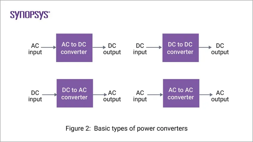
As mentioned in the previous sections, power electronic circuits control the input and output power. There are several types of power converters based on the type of application. When we consider the power source, there are two main types of power sources, namely alternating current (AC) and direct current (DC). This forms four basic types of power electronics circuits shown in the figure below.
1. AC-to-DC Converters
The input AC voltage is converted to DC voltage at required levels. A diode bridge rectifier is traditionally used for these applications. But this configuration results in currents that have high peak values and high harmonic content. Boost converters are commonly used to draw currents that are in phase with the AC voltage.
2. DC-to-DC Converters
The DC power input, whether unregulated or regulated, is converted to regulated DC power at the output. Without power electronic converters, it is very difficult to generate variable DC power. With the availability of different configurations of DC-to-DC converters, DC power at desired levels has become indispensable. Buck, boost, and buck-boost converters are three basic converters that can step down, step up, and provide both levels, respectively.
3. DC-to-AC Converters (commonly known as inverters)
The input DC power from batteries is inverted to provide AC power. This AC power is used to control AC motors with precision and efficiency. A combination of AC-to-DC and DC-to-AC converters are used in high-power transmission where two different grids are connected without worrying about synchronization.
4. AC-to-AC Converters (commonly known as cycloconverters)
The AC input that has a variable magnitude and frequency is processed to provide an AC output that has both regulated magnitude and frequency. Wind power generation is a popular application of these types of converters. The output of the wind generator varies in both magnitude and frequency depending on the wind speed. To connect this power to the grid or a load, the voltage and frequency need regulation. This functionality is provided by the AC-to-AC converters.
5. power converter
Designing controllers for power electronic applications to meet high performance standards can be challenging as there can be many internal and external conditions that are not well accounted for. Factors such as system parameter changes, system operating condition changes, filtering, and delays in the measurements, may adversely affect the performance of a circuit in which the controller design is not immune to such disturbances. In this paper, the internal model design concept is explored as a viable approach for designing controllers with improved performance despite system variations. A new control strategy that improves the stability of a voltage source converter (VSC) using the internal model design concept is discussed. Conclusions show that the proposed control system can positively influence the overall dynamic response and offers better controllability despite unexpected system variations, compared to a classical decoupled control system.
Other classifications of power converters include the following:
1. Based on the isolation between input and output:
- Non-isolated Converters
- Isolated Converters
2. Based on the type of switching:
- Hard-switched Converters
- Soft-switched Converters
3. Based on the connection to the power grid:
- Grid-connected Converters
- Offline Converters.
RESULT: Hence the different theorys has been mentioned for the types of power converter circuits are employed in electric and hybrid electric vehicle
QUESTION:2
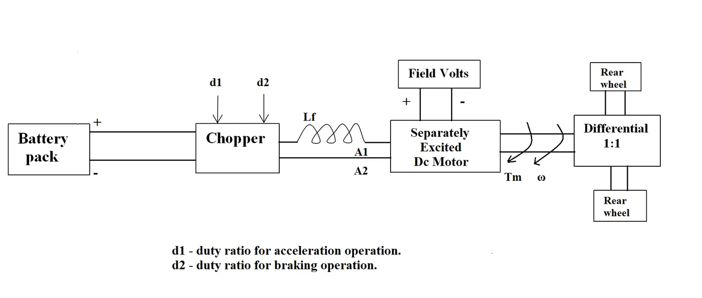
An Electric Vehicle's powertrain with 72V battery pack in shown in the diagram below. The duty ratio for acceleration operation is 'd1' and for the braking operation the duty ratio is 'd2'.
The other parameters of the electric vehicle is given below,
Motor and Controller Parameters:
Rated Armature voltage= 72 V
Rated armature current= 400 A
Ra= 0.5Ω, KΦ= 0.7 Volt second
Chopper Switching frequency= 400 Hz
The vehicle speed-torque characteristics are given by the below equation

What is EV steady state speed if duty cycle is 70%?
GIVEN DATA:
A seperately excited Dc Motor
Rated Armature voltage Va= 72 V
Rated armature current Ia= 400 A
Ra= 0.5Ω, KΦ= 0.7 Volt second
Chopper Switching frequency f= 400 Hz
Duty cycle = 70%
Torque Tv=24.7+(0.0051)ω2.............(1)
for voltage Vs=batery voltage*duty cycle
72*0.7=50.4V
form the above equations applying to the equation................
Tv=(Vs-ω.K∅)K∅/Ra
⟹(50.4-ω0.7)0.7/0.5 = (70.56 - 0.98.ω)......................(2)
Equating the above 1&2 equations
70.56 - 0.98.ω=24.7+(0.0051) ω2
0.0051ω2+0.98.ω-46.94=0
The above qudratic equations the values
steady state speed of vehicle ω=38.85 rad/s
RESULT: hence for the given data the steady state speed of vehicle is 38.85 rad/s from the above equations
QUESTION:3
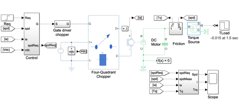
Develop a mathematical model of a DC Motor for the below equation using Simulink.
blocks used in model:
| Solver Configuration |
Defines solver settings that apply to all physical modeling blocks |
| PS-Simulink Converter |
Converts the input physical signal to a Simulink® signal |
| Controlled PWM Voltage |
Generates the signal that approximates a pulse-width modulated motor input signal |
| Four-Quadrant Chopper |
Drives the DC motor |
| DC Motor |
Converts input electrical energy into mechanical motion |
| Current Sensor |
Converts the electrical current that drives the motor into a measurable physical signal proportional to the current |
| DC Voltage Source |
Generates a DC voltage |
| Electrical Reference |
Provides the electrical ground |
| Mechanical Rotational Reference |
Provides the mechanical ground |
| Ideal Rotational Motion Sensor |
Converts the rotational motion of the motor into a measurable physical signal proportional to the motion |
| Scope |
Parameters:
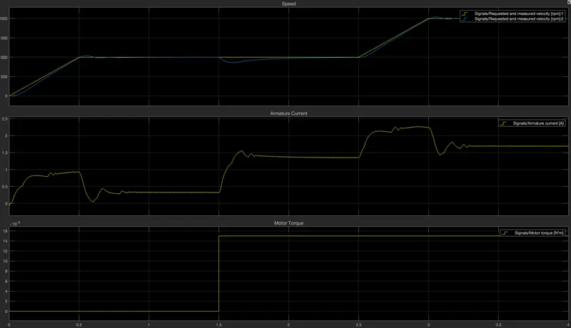
OUTPUT:
RESULT:
Induction Versus DC Brushless Motors
Brushless or Induction?
Back in the 1990s all of the electric vehicles except one were powered by DC brushless drives. Today, all the hybrids are powered by DC brushless drives, with no exceptions. The only notable uses of induction drives have been the General Motors EV-1; the AC Propulsion vehicles, including the tzero; and the Tesla Roadster.
Both DC brushless and induction drives use motors having similar stators. Both drives use 3-phase modulating inverters. The only differences are the rotors and the inverter controls. And with digital controllers, the only control differences are with control code. (DC brushless drives require an absolute position sensor, while induction drives require only a speed sensor; these differences are relatively small.)
One of the main differences is that much less rotor heat is generated with the DC brushless drive. Rotor cooling is easier and peak point efficiency is generally higher for this drive. The DC brushless drive can also operate at unity power factor, whereas the best power factor for the induction drive is about 85 percent. This means that the peak point energy efficiency for a DC brushless drive will typically be a few percentage points higher than for an induction drive.
In an ideal brushless drive, the strength of the magnetic field produced by the permanent magnets would be adjustable. When maximum torque is required, especially at low speeds, the magnetic field strength (B) should be maximum – so that inverter and motor currents are maintained at their lowest possible values. This minimizes the I² R (current² resistance) losses and thereby optimizes efficiency. Likewise, when torque levels are low, the B field should be reduced such that eddy and hysteresis losses due to B are also reduced. Ideally, B should be adjusted such that the sum of the eddy, hysteresis, and I² losses is minimized. Unfortunately, there is no easy way of changing B with permanent magnets.
In contrast, induction machines have no magnets and B fields are “adjustable,” since B is proportionate to V/f (voltage to frequency). This means that at light loads the inverter can reduce voltage such that magnetic losses are reduced and efficiency is maximized. Thus, the induction machine when operated with a smart inverter has an advantage over a DC brushless machine – magnetic and conduction losses can be traded such that efficiency is optimized. This advantage becomes increasingly important as performance is increased. With DC brushless, as machine size grows, the magnetic losses increase proportionately and part load efficiency drops. With induction, as machine size grows, losses do not necessarily grow. Thus, induction drives may be the favored approach where high-performance is desired; peak efficiency will be a little less than with DC brushless, but average efficiency may actually be better.
Permanent magnets are expensive – something like $50 per kilogram. Permanent magnet (PM) rotors are also difficult to handle due to very large forces that come into play when anything ferromagnetic gets close to them. This means that induction motors will likely retain a cost advantage over PM machines. Also, due to the field weakening capabilities of induction machines, inverter ratings and costs appear to be lower, especially for high performance drives. Since spinning induction machines produce little or no voltage when de-excited, they are easier to protect.
I almost forgot: Induction machines are more difficult to control. The control laws are more complex and difficult to understand. Achieving stability over the entire torque-speed range and over temperature is more difficult with induction than with DC brushless. This means added development costs, but likely little or no recurring costs.
The similarity of these motors is impossible to deny as are their differences. This is also true when the motors are used for more than just driving the wheels. If the AC supply voltage of an Induction Motor is removed, the result is no drive force and no battery charging regeneration effect. The motor will freewheel. This is not true of the DC Brushless motor. Both motors are driven by a variable speed frequency inverter (one AC and one DC). Regenerative braking is possible by reducing the supply frequency. The synchronous speed applied to the stators is less than the motor speed. During Regenerative Braking, the motor is generating more voltage than it is using and that excess voltage is fed back to the batteries. AC motors can be microprocessor controlled to a much finer point and thus can regenerate all the way down to a stop, whereas the Brushless DC motors regeneration capabilities tend to fade off at lower speeds. The final advantage of the AC Induction motor is in Dynamic Braking. This is done by reversing the rotating wave within the stators. By reversing the rotating wave within the motor, the motor wants to turn in the opposite direction. This does not regenerate power for the batteries, but the magnetic field in the motor spinning in the opposite direction simply acts as a brake on the spinning rotor and the excess energy is dissipated as heat. The DC Brushless motor is capable of doing this, but excess heat build-up runs the possibility of damaging the expensive rare earth magnets within its rotor.
All in all, both motors are quite good at doing what they were designed to do. The DC Brushless motors have been around a little longer in this application and have a strong foothold in the industry, but that foothold is slipping as the technology to control the Induction motor has improved. Tesla Motors has a policy of releasing its technology to other manufacturers so that they too can enter into the world of the plug-in electric vehicle
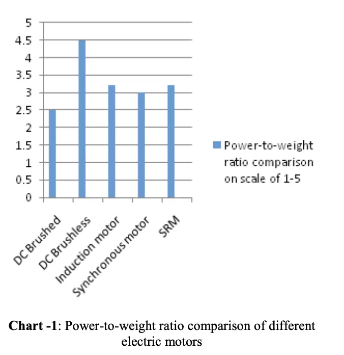
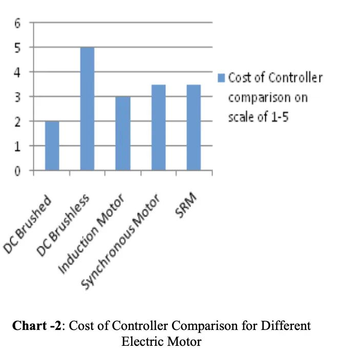
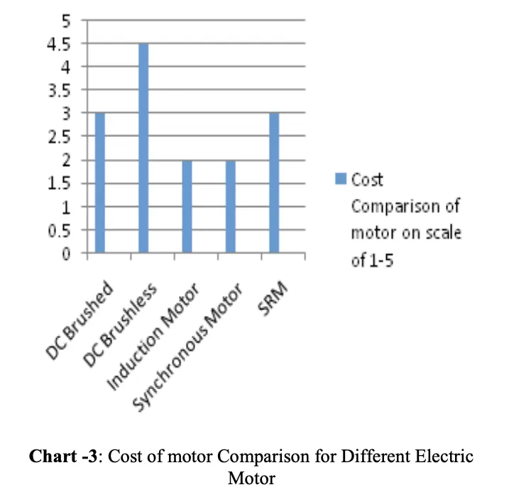
Result:Hence the results and plots of advantages and disadvantages of INDUCTION&DC BRUSHLESS MOTOR