Week-6 Challenge: EV Drivetrain
Answer:
1. Which types of power converter circuits are employed in electric and hybrid electric vehicle?
Introduction
The large number of automobiles in use around the world has caused and continues to cause serious problems of environment and human life. Air pollution, global warming, and the rapid depletion of the earth’s petroleum resources are now serious problems. Electric Vehicles (EVs), Hybrid Electric Vehicles (HEVs) and Fuel Cell Electric Vehicles (FCEVs) have been typically proposed to replace conventional vehicles in the near future. Most electric and hybrid electric configurations use two energy storage devices, one with high energy storage capability, called the “main energy system” (MES), and the other with high power capability and reversibility, called the “rechargeable energy storage system” (RESS). MES provides extended driving range, and RESS provides good acceleration and regenerative braking. Energy storage or supply devices vary their output voltage with load or state of charge and the high voltage of the DC-link create major challenges for vehicle designers when integrating energy storage / supply devices with a traction drive. DC-DC converters can be used to interface the elements in the electric power train by boosting or chopping the voltage levels. Due to the automotive constraints, the power converter structure has to be reliable, lightweight, small volume, with high efficiency, low electromagnetic interference and low current/voltage ripple. Thus, in this chapter, a comparative study on three DC/DC converters topologies (Conventional step-up dc-dc converter, interleaved 4-channels step-up dc-dc converter with independent inductors and Full-Bridge step-up dc-dc converter) is carried out. The modeling and the control of each topology are presented. Simulations of 30KW DC/DC converter are carried out for each topology. This study takes into account the weight, volume, current and voltage ripples, Electromagnetic Interference (EMI) and the efficiency of each converter topology.
Electric vehicles powertrain
An Electric Vehicle is a vehicle that uses a combination of different energy sources, Fuel Cells (FCs), Batteries and Supercapacitors (SCs) to power an electric drive system. In EV the main energy source is assisted by one or more energy storage devices. Thereby the system cost, mass, and volume can be decreased, and a significant better performance can be obtained. Two often used energy storage devices are batteries and SCS. They can be connected to the fuel cell stack in many ways. A simple configuration is to directly connect two devices in parallel, (FC/battery, FC/SC, or battery/SC). However, in this way the power drawn from each device cannot be controlled, but is passively determined by the impedance of the devices. The impedance depends on many parameters’ temperature, state-of-charge, health, and point of operation. Each device might therefore be operated at an inappropriate condition, health and efficiency. The voltage characteristics also have to match perfectly of the two devices, and only a fraction of the range of operation of the devices can be utilized, in a fuel cell battery configuration the fuel cell must provide almost the same power all the time due to the fixed voltage of the battery, and in a battery/supercapacitor configuration only a fraction of the energy exchange capability of the supercapacitor can be used. This is again due to the nearly constant voltage of the battery. By introducing DC/DC converters one can chose the voltage variation of the devices and the power of each device can be controlled electric vehicle drive system.
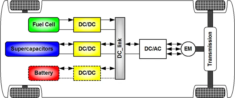
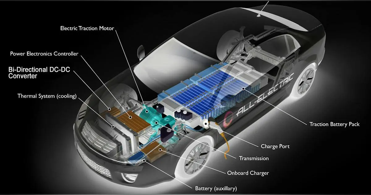
In reference 10 cases of combining the fuel cell with the battery, SCs, or both are investigated. The system volume, mass, efficiency, and battery lifetime were compared. It is concluded that when SCs are the only energy storage device the system becomes too big and heavy. A fuel cell/battery/supercapacitors hybrid provides the longest life time of the batteries. It can be noticed that the use of high power DC/DC converters is necessary for EV power supply system. The power of the DC/DC converter depends on the characteristics of the vehicle such as top speed, acceleration time from 0 to 100 Km/h, weight, maximum torque, and power profile Generally, for passenger cars, the power of the converter is more than 20 KW and it can go up to 100 KW.
DC/DC converters for electric vehicles
The different configurations of EV power supply show that at least one DC/DC converter is necessary to interface the FC, the Battery or the Supercapacitors module to the DC-link.
In electric engineering, a DC-to-DC converter is a category of power converters and it is an electric circuit which converts a source of direct current (DC) from one voltage level to another, by storing the input energy temporarily and then releasing that energy to the output at a different voltage. The storage may be in either magnetic field storage components (inductors, transformers) or electric field storage components (capacitors).
DC/DC converters can be designed to transfer power in only one direction, from the input to the output. However, almost all DC/DC converter topologies can be made bi-directional. A bi-directional converter can move power in either direction, which is useful in applications requiring regenerative braking.
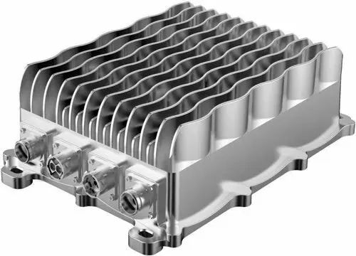
The amount of power flow between the input and the output can be controlled by adjusting the duty cycle, Usually, this is done to control the output voltage, the input current, the output current, or to maintain a constant power. Transformer-based converters may provide isolation between the input and the output. The main drawbacks of switching converters include complexity, electronic noise and high cost for some topologies. Many different types of DC/DC power converters are proposed in literature. The most common DC/DC converters can be grouped as
Non-isolated converters
The non-isolated converters type is generally used where the voltage needs to be stepped up or down by a relatively small ratio (less than 4:1). And when there is no problem with the output and input having no dielectric isolation. There are five main types of converters in this non-isolated group, usually called the buck, boost, buck-boost, Cuk and charge-pump converters. The buck converter is used for voltage step-down, while the boost converter is used for voltage step-up. The buck-boost and Cuk converters can be used for either step-down or step-up. The charge-pump converter is used for either voltage step-up or voltage inversion, but only in relatively low power applications.
Isolated converters
Usually, in this type of converters a high frequency transformer is used. In the applications where the output needs to be completely isolated from the input, an isolated converter is necessary. There are many types of converters in this group such as Half-Bridge, Full-Bridge, Fly-back, Forward and Push-Pull DC/DC converters. All of these converters can be used as bi-directional converters and the ratio of stepping down or stepping up the voltage is high.
Electric vehicle converters requirements
In case of interfacing the Fuel Cell, the DC/DC converter is used to boost the Fuel Cell voltage and to regulate the DC-link voltage. However, a reversible DC/DC converter is needed to interface the SCs module. A wide variety of DC-DC converters topologies, including structures with direct energy conversion, structures with intermediate storage components However some design considerations are essential for automotive applications:
- Light weight,
- High efficiency,
- Small volume,
- Low electromagnetic interference,
- Low current ripple drawn from the Fuel Cell or the battery,
- The step-up function of the converter,
- Control of the DC/DC converter power flow subject to the wide voltage variation on the converter input.
Each converter topology has its advantages and its drawbacks. For example, The DC/DC boost converter does not meet the criteria of electrical isolation. Moreover, the large variance in magnitude between the input and output imposes severe stresses on the switch and this topology suffers from high current and voltage ripples and also big volume and weight. A basic interleaved multichannel DC/DC converter topology permits to reduce the input and output current and voltage ripples, to reduce the volume and weight of the inductors and to increase the efficiency. These structures, however, work efficiently when a high voltage step-up ratio is required since the duty cycle is limited by circuit impedance leading to a maximum step-up ratio of approximately 4. Hence, two series connected step-up converters would be required to achieve the specific voltage gain of the application specification. A full-bridge DC/DC converter is the most frequently implemented circuit configuration for fuel-cell power conditioning when electrical isolation is required. The full bridge DC/DC converter is suitable for high-power transmission because switch voltage and current are not high. It has small input and output current and voltage ripples. The full-bridge topology is a favorite for zero voltage switching (ZVS) pulse width modulation (PWM) techniques.
Electromagnetic compatibility regulation
Fast semiconductor devices make it possible to have high speed and high frequency switching in power electronics converters. High speed switching helps to reduce weight and volume of equipment; however, it causes some undesirable effects such as radio frequency interference (RFI) emission. It is believed that high dv/dt or di/dt due to modern power device switching is mainly responsible for the EMI emissions. Application of electrical equipment especially static power electronic converters in different equipment is increasing more and more. Power electronics converters are considered as an important source of electromagnetic interference and have undesirable effects on the electric networks. Some residential, commercial and especially medical consumers are very sensitive to power system disturbances including voltage and frequency variations. Also, for Electric vehicle, there is limitation of the EMI. The best solution to reduce the interference and improve the power quality is complying national or international EMC regulations. CISPR, IEC, FCC and VDE are among the organizations from Europe, USA and Germany who are responsible for determining and publishing the most important EMC regulations. Compliance of regulations is evaluated by comparison of measured or calculated conducted interference level in the mentioned frequency range with the stated requirements in regulations. In European community compliance of regulation is mandatory and products must have certified label to show covering of requirements For Electric Vehicle, the maximum interference level should meet the DIN VDE 0879 standard. The limits in this standard are almost the same as the class B of VDE 0871 requirement and limitation on conducted emission.
Electromagnetic conducted interference measurement
A Line Impedance Stabilization Network (LISN) is typically designed to allow for measurements of the electromagnetic interference existing on the power line, it is a device used to create known impedance on power lines of electrical equipment during electromagnetic interference testing. The stated situation is shown in
Variation of level of signal at the output of LISN versus frequency is the spectrum of interference. The electromagnetic compatibility of a device can be evaluated by comparison of its interference spectrum with the standard limitations. The level of signal at the output of LISN in frequency range 10 kHz up to 30 MHz or 150 kHz up to 30 MHz is criteria of compatibility and should be under the standard limitations. Converting the results to dBuV makes it possible to compare the spectrum of interference with standard requirements. In practical situations, the LISN output is connected to a spectrum analyzer and interference measurement is carried out. But for modeling and simulation purposes, the LISN output spectrum must be calculated using appropriate software.
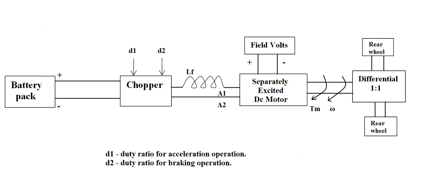
2. An Electric Vehicle's powertrain with 72V battery pack in shown in the diagram below. The duty ratio for acceleration operation is 'd1' and for the braking operation the duty ratio is 'd2'.
The other parameters of the electric vehicle is given below,
Motor and Controller Parameters:
Rated Armature voltage= 72 V
Rated armature current= 400 A
Ra= 0.5Ω, KΦ= 0.7 Volt second
Chopper Switching frequency= 400 Hz
The vehicle speed-torque characteristics are given by the below equation

What is EV steady state speed if duty cycle is 70%?
Answer:
Given data
Rated Armature voltage= 72 V
Rated armature current= 400 A
Ra= 0.5Ω,
KΦ= 0.7 Volt second
Chopper Switching frequency= 400 Hz
Duty cycle = 70%
Speed torque characteristics
Tv = 24.7 + (0.0051)w^2
Solution
Duty Cycle = 70%
Voltage = Va × duty cycle
= 72 × 0.7
V = 50.4
Torque, T = KΦ/R *[ V - KΦ*ω]
By Substituting the given values,
Torque, T = ( 0.7 / 0.5 ) * ( 50.4−0.7w )
= 1.4 × (50.4 – 0.7 w)
= 70.56 – 0.98 w
T = 70.56 – 0.98 w
Torque = speed toque characteristics
T = Tv
70.56 – 0.98 w = 24.7 + (0.0051)w^2
0.0051w^2 + 098w + 24.7 - 70.56
0.0051w^2 + 0.98w - 45.86=0
Using Quadratic equation
X = 38.915
X = −231.072
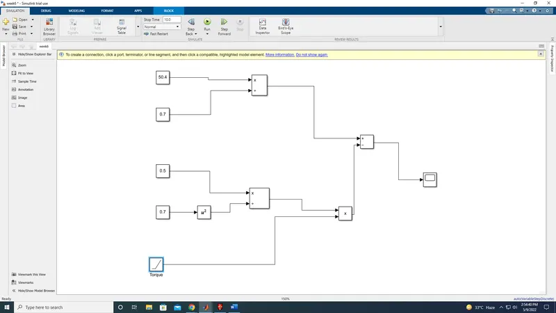
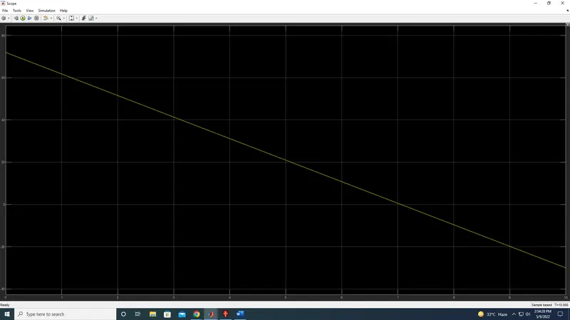
3. Develop a mathematical model of a DC Motor for the below equation using Simulink.
Answer:
V = 5.4
KΦ = 0.7
Ra = 0.5
Assume T = 60
4. Refer to the blog on below topic:
Induction Versus DC brushless motors by Wally Rippel, Tesla
Explain in brief about author’s perspective.
Answer:
1. There is no such thing called the best engine. According to the personal requirements, we need to adapt the engine type.
2. In the course of time, Lead-acid batteries are replaced by Lithium-ion batteries.
3. In the course of time, DC brush motors are replaced by DC Brushless or Induction Motors.
4. In the course of time, Contactor Controllers are replaced by Modulating Inverters.
5. There is a bigger concern regarding the stable use of these elements mentioned above over the next few decades.
6.The author discusses the two technologies such as: 1. DC Brushless Drives and 2. Induction Motor with it's feature of operation.
7. He says brushless motors are useless motors without the inverter.
8. He also mentioned that the 3-phase induction motor has great utility but with several limitations.
9. The major limitation being, the Induction Motor can not operate from DC, and AC is a must.\
10. Further, he compares the future trends which may occur in DC Brushless as well as in Induction motor.
Conclusion:
He concludes that DC brushless drives will likely continue to dominate in the hybrid and coming plug-in hybrid markets, and that
induction drives will likely maintain dominance for the high-performance pure electrics.