Week-6 Challenge: EV Drivetrain
1 ) Which type of power converter circuits are employed in an electric and hybride electric vehicles ?
The types of power converter circuits are employed in an electric and hybrid electric vehicles are as follow :
DC -DC converter :
- DC-DC converter is a category of power converter and it is an electric circuit which converts a source of direct current from one voltage level to another , by storing the input energy temporarily and then releasing that energy to the output at a different voltage . The storage may be in either magnetic field storage components (inductors , transformers) or electric field storage components (capacitors).
- DC-DC converters can be designed to transfer power in only one direction , from the input to the output . However , almost all DC-DC converter topologies can be made bi - directional.
- A bi-directional converter can move power in either direction ,which is useful in applications requiring regenerative braking .
AC-DC converter :
- The AC-DC converter is essential to work more proficiently to cut the charging time .
- The AC-DC converter consists of a power factor correction (PFC) which converts input AC voltage to DC voltage , an H- bridge circuit which convert the DC voltage into high - frequency AC voltage , a high- frequency transformer which regulates transformation and insulation , and a circuit which rectifies and smooths high - frequency AC voltages .
- The problem with AC-DC converter is that it includes big power loss in high- frequency switching .
DC-AC converter :
- The DC-AC converter (inverter ) comprise six bidirectional semiconductors (IGBT) .
- The main source of electric power is the battery which is DC source .
- The DC output of the battery is boosted according to the requirement and then converted into AC using a DC-AC inverter .
- The function of an inverter is to change a DC input voltage to asymmetric AC output voltage of desired magnitude and frequency .
AC -AC converter :
- AC-AC converter converts an AC waveform to another AC waveform, where the output voltage and frequency can be set randomly .
- This change is mainly essentional in case of speed controlling of machine , for low frequency and variable voltage magnitude application .
2 ) An Electric Vehicle's powertrain with 72V battery pack in shown in the diagram below. The duty ratio for acceleration operation is 'd1' and for the braking operation the duty ratio is 'd2'.
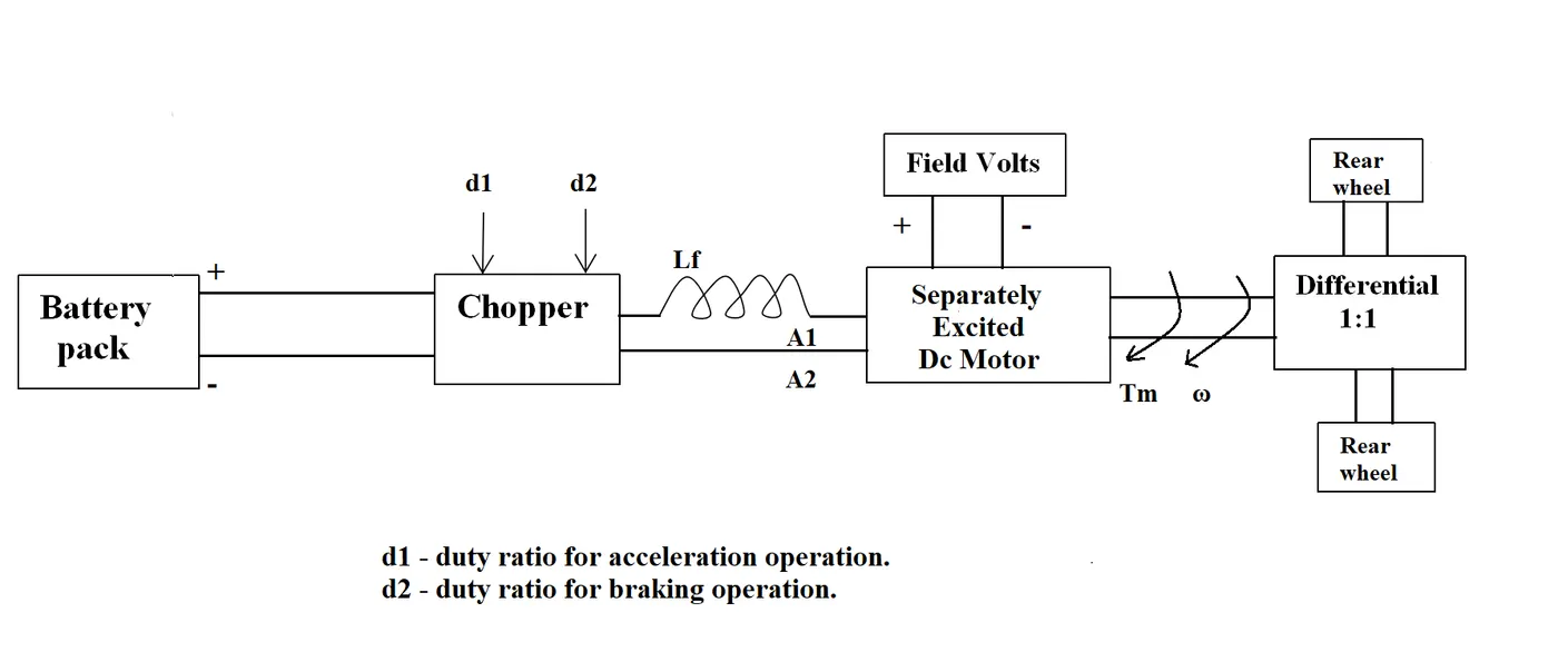
What is EV steady state speed if duty cycle is 70%?
Given data :
Rated armature voltage = Vr = 72 v ,
Rated armature current = Ia = 400 A ,
Rated armature resistance = Ra = 0.5 ohms ,
Motor constant = `kphi = 0.7 Vs` ,
Frequency = f = 400 Hz ,
Duty cycle = 70 % = 0.7 ,
`T = 24.7 + 0.0051(omega)^2` ............................equation 1
Calculations :
v = vr * duty cycle
= 72 * 0.7
= 50.4 v
`T = V (kphi)/(Ra) - (kphi)^2/(Ra) * omega`
= `50.4*(0.7/0.5) - ((0.7)^2 /0.5) * omega`
= `70.56 - 0.98 omega`...................equation 2
Using quadratic equation to solve the roots and considering only positive roots because the speed cannot be negative .
`omega = (( -0.98 + ((0.98)^2 - 4 * 0.005*(-45.86))^(1/2)) /2 *0.0051`
= 38.915 rad/sec
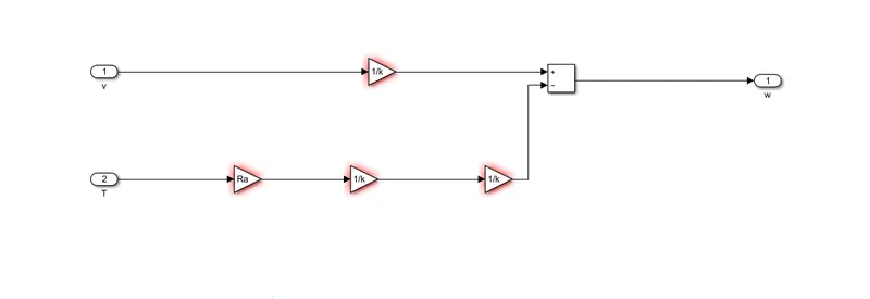
3. ) Develop a mathematical model of a DC Motor for the below equation using Simulink.
`omega = V/(Kphi) - (Ra)/(Kphi)^2*T`
- Here we have given input port for V and T.
- Gain block is used for constant Ra and K.
- `omega` is obtained in output port.
Below is the link of the model,
https://drive.google.com/file/d/1APyOExOendB-XJtrEiqV6bgVViDKJOsU/view?usp=sharing
4 ) Refer to the blog " Induction vs DC brushless motors by wally Rippel ,Tesla "
Explain in brief about auther's perspective .
Here the auther generally talks about the difference between the induction motors and brushless dc motor. The working principle of both the motor . Application and disadvantages of both type of motors . At last he gives the conclusion about the future use of both the motors .
Working of DC brushless motor :
- The rotor includes two or more permanent magnets that generate DC magnetic field .
- The magnetic field enters the stator core and interacts with currents flowing within the windings to produce torque interaction between stator and rotor.
- Magnitude and polarity of the stator current must be continuously varied in right way , so that torque remain constant and the conversion of electric to mechanical energy is efficient .
- The device which provides this current control is called an inverter.
Working of induction motor :
- The induction rotor has no magnets -just stacked steel laminations with buired peripheral conductors that form a "shorted structure ".
- Current flowing in the stator winding produce a rotating magnetic field that enter the rotor .
- The frequency of this magnetic field is equal to the difference between the applied electric frequency and the rotational frequency of the rotor .
- Due to diffeence bitween the rotor and electrical frequency ,voltage is induced .
- In response to this voltage , currents are prouced within the rotor conductor.
- when a 3 - phase induction motor is connected to utility type 3 - phase power ,torque is produced .'The motor has ability to start under load .
- No inverter is needed .
Comparision between brushless and induction motor .
Both brushless and induction motor use motor having similar stators . Both drives use 3 - phase modulating inverters . DC brushless drives require an absolute position sensor , while induction drive require only speed sensor .
Heat generated with DC brushless drive is very less .The peak point energy efficiency for a DC brushless drive will typically be a few percentage point higher than for an induction drive .
In brushless drive , the strenghth of the magnetic field produced by the permanent magnets would be adjustable .when maximum torque is required at low speed , the magnetic field strength (B) should be maximum so that inverter and motor current are maintained at their lowest possible values .Ideally B should be adjusted such that the sum of the eddy , hysteresis and heat losses is minimized . But thee is no easy way of changing B with permenent magnets .
In an induction motor having no magnet ,B can be adjustable . B is proportional to v/f . Thus , the induction machine when operated with a smart inverter has an advantage over a DC brushless machine .
Cost of permenent magnet is very high .So the induction motor will likeky retain a cost advantage over DC brushless motor .
Induction machine are more difficult to cotrol . Achieving stability over temperature and torque-speed range is difficult with induction than with DC brushless .
Future uses of both the motor in EV :
DC brushless drive will likely continue to dominate in hybrid and coming plug in hybrid markets and induction drive will likely maintained dominance for high -performance pure electrics .