Week-6 Challenge: EV Drivetrain
Aim: Which types of power converter circuits are employed in an electric and hybrid electric vehicle?
DC-DC power converters: The different configurations of EV power supply show that at least one DC/DC converter is necessary to interface the FC, the Battery, or the Supercapacitors module to the DC-link. In electric engineering, a DC to DC converter is a category of power converters and it is an electric circuit that converts a source of direct current (DC) from one voltage level to another, by storing the input energy temporarily and then releasing that energy to the output at a different voltage. The storage may be in either magnetic field storage components (inductors, transformers) or electric field storage components (capacitors).
The amount of power flow between the input and the output can be controlled by adjusting the duty cycle (ratio of on/off time of the switch). Usually, this is done to control the output voltage, the input current, the output current, or to maintain constant power.
Non-isolated converters:
The non-isolated converters type is generally used where the voltage needs to be stepped up or down by a relatively small ratio (less than 4:1). And when there is no problem with the output and input having no dielectric isolation. There are five main types of converter in this non-isolated group, usually called the buck, boost, buck-boost, Cuk and charge-pump converters. The buck converter is used for voltage step-down, while the boost converter is used for voltage step-up. The buck-boost and Cuk converters can be used for either step-down or step-up. The charge-pump converter is used for either voltage step-up or voltage inversion, but only in relatively low power applications.
Isolated converters:
Usually, in this type of converter, a high-frequency transformer is used. In the applications where the output needs to be completely isolated from the input, an isolated converter is necessary. There are many types of converters in this group such as Half-Bridge, Full-Bridge, Fly-back, forwarding and Push-Pull DC/DC converters All of these converters can be used as bi-directional converters and the ratio of stepping down or stepping up the voltage is high.
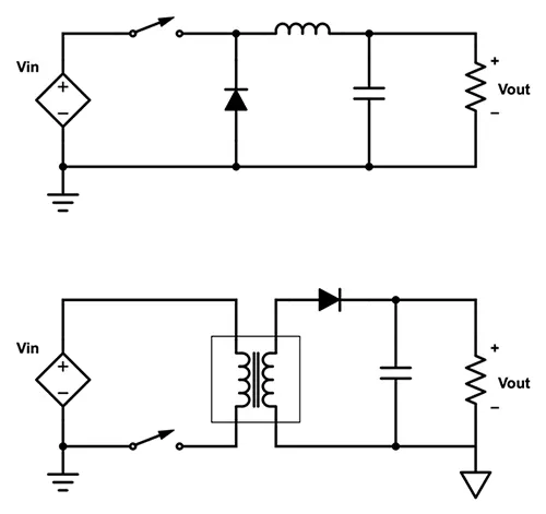
Electric vehicle converter's requirements
In case of interfacing the Fuel Cell, the DC/DC converter is used to boost the Fuel Cell voltage and regulate the DC-link voltage. However, a reversible DC/DC converter is needed to interface the SCs module. A wide variety of DC-DC converters topologies, including structures with direct energy conversion, and structures with intermediate storage components (with or without transformer coupling). However, some design considerations are essential for automotive applications:
-
Lightweight,
-
High efficiency,
-
Small volume,
-
Low electromagnetic interference,
-
Low current ripple drew from the Fuel Cell or the battery,
-
The step-up function of the converter,
-
Control of the DC/DC converter power flow subject to the wide voltage variation on the converter input.
An Electric Vehicle's powertrain with 72V battery pack in shown in the diagram below. The duty ratio for acceleration operation is 'd1' and for the braking operation the duty ratio is 'd2'.
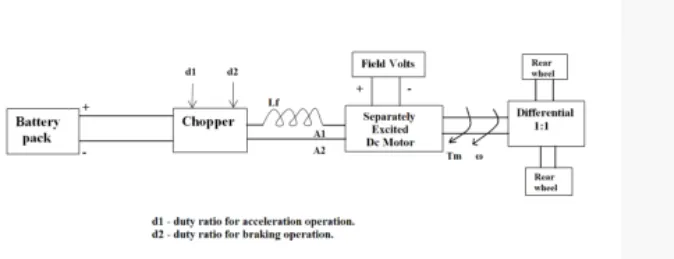
Given values:
Vbat = 72v
Va = 72v
Ia = 400A
Ra = 0.5 ohm
K`phi` = 0.7v sec
Chopper fsw = 400 hz
Torque equation = 24.7+0.0051ω^2
Duty cycle = 70%
Know assuming there is noback EMF
the supply voltage Vs = Vbat * dutycycle
Vs = 0.7* 72
= 50.4V
T = (K`phi`*Vs/ Ra) - ((K`phi`)^2/Ra)*ω
T = (0.7*50.4)/0.5 - (0.7^2/0.5 )*ω
70.56-0.98ω = 24.7 + 0.0051ω^2
0.0051ω^2+0.98ω-45.86 = 0
After solving the above Quadratic equation
ω = -231.7 rad /s
or +38.91 rad/s
we will use the positive value as speed can't be negative
therefore the steady-state speed of the EV is 38.91 rad/s. which is approximate 372 RPM.
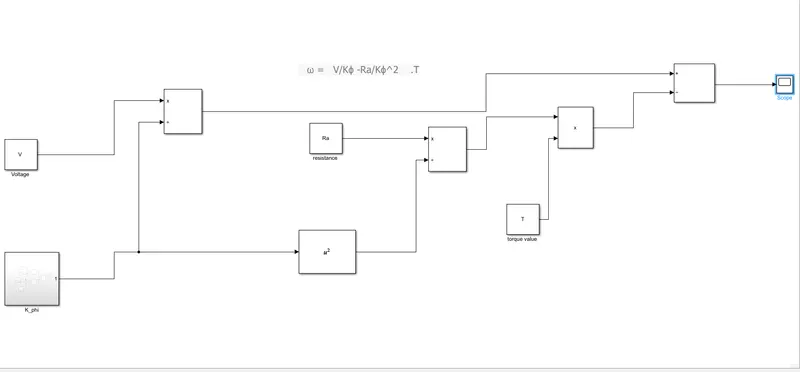
Develop a mathematical model of a DC Motor for the below equation using Simulink.
ω= V/Kϕ -Ra/Kϕ^2 .T
The mathematical model for a given equation :
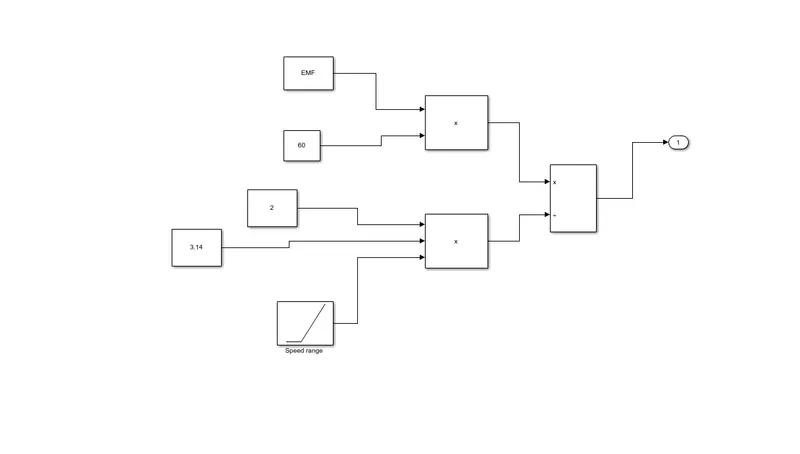
Subsystem:
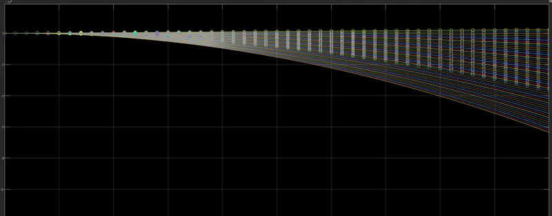
Result:
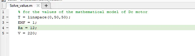
Input values:
Block explanation:
- the constant blocks are used to provide the values of voltage, EMF, resistance, and the values of torque from 0 to 50 Nm
- the addition, subtraction, product, and division are done by using the Add, product, and divide blocks.
- The Square block is used to square the value k
- for finding the value of K_phi subsystem block is used.
- the Ramp block is used to provide the speed ranges.
- the scope is shown to get the values from the given model.
Refer to the blog on below topic:
Induction Versus DC brushless motors by Wally Rippel, Tesla
Explain in brief about the author’s perspective. The author's perspective can be understood in the following points :
- The author basically tries to solve the dilemma between the Dc brushless motor and the Induction motor uses
- He directly stated that the uses of different motors are purely based on the different requirements factors like efficiency, market capability, and requirement, Performance, type of vehicle such as HEV or EV, etc.
- He also emphasizes the construction, pros, and cons of the Dc brushless and the Induction motor
- He also differentiates between the two motors on the basis of cost, on the basis of handability, on the basis of controls, weight, power, and the usage of inverters
- He also stated that according to him the DC brushless motor with inverter used in HEV and the induction motor with the smart inverter are compatible with high performance EV