Week-6 Challenge: EV Drivetrain
1. Which types of power converter circuits are employed in electric and hybrid electric vehicle?
An integral part of any modern day electric vehicle is power electronic circuits (PECs) comprising of DC-AC inverters and DC-DC converters. A DC-AC inverter supplies the high power electric motor and utility loads such as air-conditioning system, whereas a DC-DC converter supplies conventional low-power, low-voltage loads.
Power converter: A power converter is an electrical circuit that changes the electric energy from one form into the desired form optimized for the specific load. A converter may do one or more functions and give an output that differs from the input. It is used to increase or decrease the magnitude of the input voltage, invert polarity, or produce several output voltages of either the same polarity with the input, different polarity, or mixed polarities such as in the computer power supply unit.
The DC to DC converters are used in a wide range of applications including computer power supplies, board level power conversion and regulation, dc motor control circuits and much more.
The converter acts as the link or the transforming stage between the power source and the power supply output. There are several kings of converters based on the source input voltage and the output voltage and these falls into four categories namely the AC to DC converter known as the rectifier, the AC to AC clycloconverter or frequency changer, the DC to DC voltage or current converter, and the DC to AC inverter.
The power semiconductor devices or power electronic converters are four categories :
- AC to DC Converter (Controlled Rectifier)
- DC to DC Converter (DC Chopper)
- AC to AC Converter (AC voltage regulator)
- DC to AC Converter (Inverter)
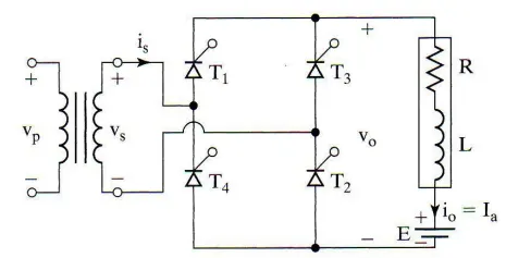
1. AC to DC Converter : An AC to DC converter circuit can convert AC voltage into a DC voltage. The DC output voltage can be controlled by varying the firing angle of the thyristors. The AC input voltage could be a single phase or three phase.
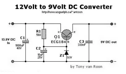
2. DC to DC Converter: These converters can converter a fixed DC input voltage into variable DC voltage or vice versa. The DC output voltage is controlled by varying of duty cycle.
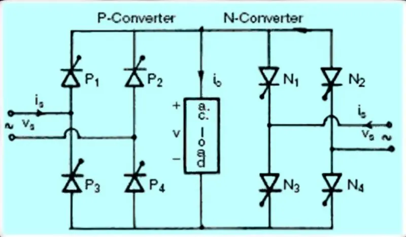
3. AC to AC Converter: This converters can convert from a fixed ac input voltage into variable AC output voltage. The output voltage is controlled by varying firing angle of TRIAC. These type converters are known as AC voltage regulator.
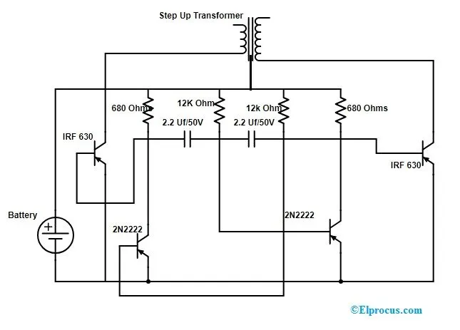
4. DC to AC Converter: DC to AC converters is mainly designed for changing a DC power supply to an AC power supply. Here, DC power supply is comparatively stable as well as positive voltage source whereas AC oscillates approximately a 0V base stage, typically in a sinusoidal or square or mode. The common inverter technology used in electronics is to convert a voltage source from a battery into an AC signal. Generally, they operate with 12 volts and commonly used in applications like automotive, lead-acid technology, photovoltaic cell, etc. A transformer coil system & a switch is the simple circuit used for an inverter. A typical transformer can be connected toward the DC signal’s input through a switch to oscillate back quickly. Due to the current flow in bi-directional in the primary coil of the transformer, an alternating current signal is an output throughout the secondary coils.
These power converters are employed electric and hybrid electric vehicles.
2. An Electric Vehicle's powertrain with 72V battery pack in shown in the diagram below. The duty ratio for acceleration operation is 'd1' and for the braking operation the duty ratio is 'd2'.
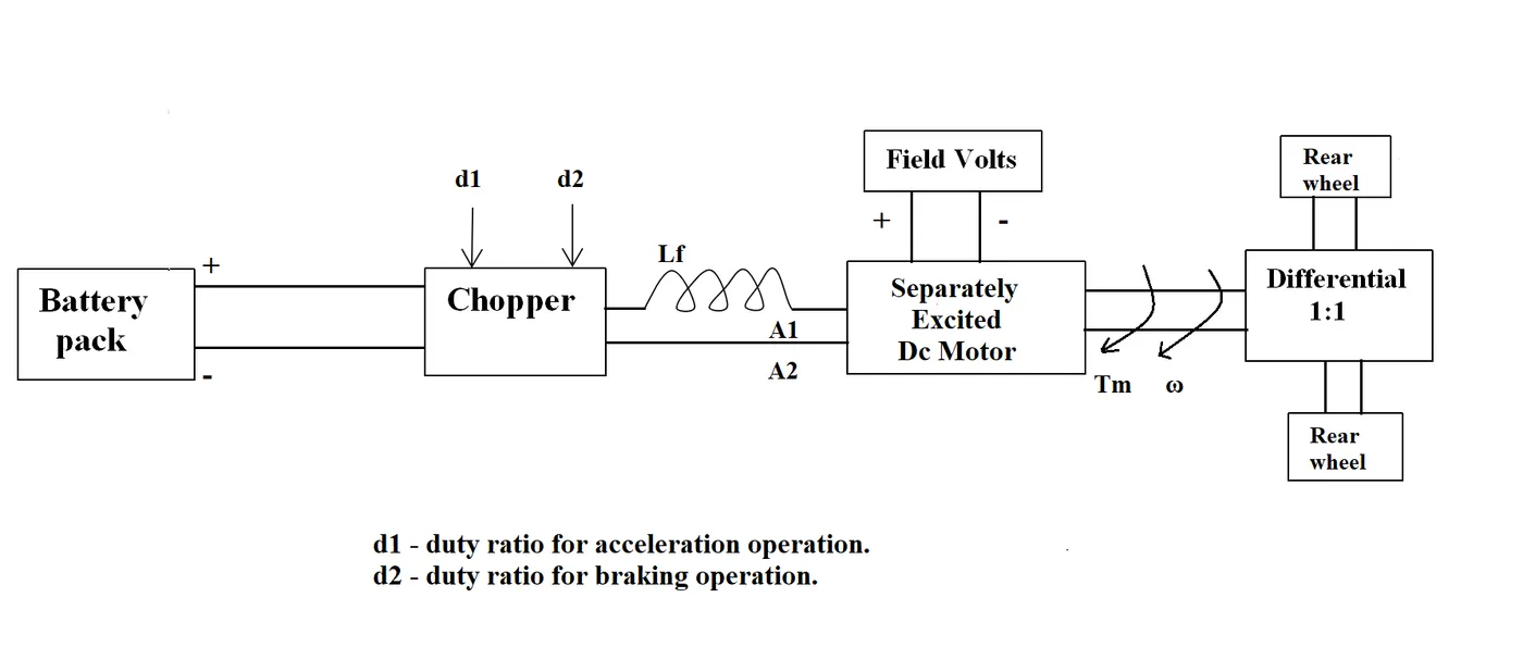
The other parameters of the electric vehicle is given below,
Motor and Controller Parameters:
Rated Armature voltage= 72 V
Rated armature current= 400 A
Ra= 0.5Ω, KΦ= 0.7 Volt second
Chopper Switching frequency= 400 Hz
The vehicle speed-torque characteristics are given by the below equation

What is EV steady state speed if duty cycle is 70%?
Solution:
Given
Rated Armature voltage= 72 V,
Rated armature current= 400 A,
Ra= 0.5Ω,
KΦ= 0.7 Volt second,
Chopper Switching frequency= 400 Hz,
Duty cycle = 70% = 0.7
Battery voltage/ input voltage = 72 V
The Output voltage = 0.7 * 72 = 50.4 V
Torque Equation,
T = (V*k)/Ra- (K^2)*w/Ra
T= Torque
V = Armature voltage
R = Armature Resistance
w = Speed rad/sec
Compare the two equations
(v*k)/Ra - (k^2) * w/Ra = 24.7 + 0.0051*w^2
(72*0.7)/0.5 - (0.7^2) * w/0.5 = 24.7 + 0.0051*w^2
70.56 - 0.98*w = 24.7 + 0.0051*w^2
w^2 + 192.15*w - 8992.15 = 0
We get w = 38.91, -231.07
As the speed value can not be negative
w = 38.91 rad / sec.
3. Develop a mathematical model of a DC Motor for the below equation using Simulink.
ω= V/Kϕ -Ra/Kϕ^2 .T
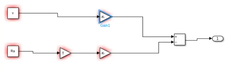
This is how to develop a model of a dc motor of equation by using simulink.
4. Refer to the blog on below topic:
Induction Versus DC brushless motors by Wally Rippel, Tesla
Explain in brief about author’s perspective.
According to the blog Induction versus DC brushless motors by wally rippel, tesla, the writer state the changes in the world years ego and latest technological trends that are happening in EV related to dc brushless motor and induction motor.
Induction Motor:
Induction motor drives of the three phase induction motor was invented by Nikola Tesla sometime before 1889. Curiously, the stators for the 3-phase induction motor and the DC brushless motor are virtually identical. Both have three sets of distributed windings that are inserted within the stator core. The essential difference between the two machines is with the rotor. When a 3-phase induction motor is connected to utility type 3-phase power, torque is produced at the outset; the motor has the ability to start under load. No inverter is needed. The fact that induction motors are directly compatible with conventional utility power is the main reason for their success. In contrast, a brushless DC motor produces no starting torque when directly connected to fixed frequency utility power. They really need the aid of an inverter whose phase is maintained in step with the angular position of the rotor. While 3-phase induction motors have great utility, they also have some severe limitations. They cannot operate from DC; AC is a must. Shaft speed is proportionate to line frequency. Hence, when used with utility power, they are constant speed machines. Finally, when operated from utility power, they have limited starting torque and somewhat limited running peak torque capabilities, when compared to DC type machines.
Add an inverter (without any feedback control) and it becomes possible to power an induction machine from a battery or other DC source; variable speed also becomes possible simply by adjusting the inverter frequency. Still, torque performance is low compared with DC machines. Add some feedback loops such that the inverter produces the exact frequency that the motor desires and the induction motor is now capable of competing with DC and DC brushless for vehicle applications.
Brushless DC Motor:
Differences:
According to him both DC brushless and induction drives use motors having similar stators. Both drives use 3-phase modulating inverters. The only differences are the rotors and the inverter controls. And with digital controllers, the only control differences are with control code. DC brushless drives require an absolute position sensor, while induction drives require only a speed sensor; these differences are relatively small.
One of the main differences is that much less rotor heat is generated with the DC brushless drive. Rotor cooling is easier and peak point efficiency is generally higher for this drive. The DC brushless drive can also operate at unity power factor, whereas the best power factor for the induction drive is about 85 percent. This means that the peak point energy efficiency for a DC brushless drive will typically be a few percentage points higher than for an induction drive.
In an ideal brushless drive, the strength of the magnetic field produced by the permanent magnets would be adjustable. When maximum torque is required, especially at low speeds, the magnetic field strength (B) should be maximum – so that inverter and motor currents are maintained at their lowest possible values. This minimizes the I² R (current² resistance) losses and thereby optimizes efficiency. Likewise, when torque levels are low, the B field should be reduced such that eddy and hysteresis losses due to B are also reduced. Ideally, B should be adjusted such that the sum of the eddy, hysteresis, and I² losses is minimized. Unfortunately, there is no easy way of changing B with permanent magnets.
In contrast, induction machines have no magnets and B fields are “adjustable,” since B is proportionate to V/f (voltage to frequency). This means that at light loads the inverter can reduce voltage such that magnetic losses are reduced and efficiency is maximized. Thus, the induction machine when operated with a smart inverter has an advantage over a DC brushless machine – magnetic and conduction losses can be traded such that efficiency is optimized. This advantage becomes increasingly important as performance is increased. With DC brushless, as machine size grows, the magnetic losses increase proportionately and part load efficiency drops. With induction, as machine size grows, losses do not necessarily grow. Thus, induction drives may be the favored approach where high-performance is desired; peak efficiency will be a little less than with DC brushless, but average efficiency may actually be better.
This is the brief explanation of induction motor and brushless dc motor.