Week-6 Challenge: EV Drivetrain
Q.1. Which types of power converter circuits are employed in an electric and hybrid electric vehicle?
Ans:-
- A motor drive consists of a power converter and a controller. the power electronic converter handles the flow of bulk power from the source to the motor input terminals. the controller processes the command input and the feedback information to generate the switching signals for the power converter
- The power converter can be a DC drive supplying a DC motor or an AC drive supplying an AC motor.
- A DC/DC converter in its basic form converts unregulated DC input voltage at a certain level to regulated DC output voltage at a different level with very high conversion efficiency. These are operated at a very high frequency. The switches are turned ON and OFF by pulse width modulation (PWM).
- The power converter is made of high-power fast-acting semi converter devices, such as a bipolar junction transistor such as MOSFET, IGBT, SCR, GTO, and MCT.
- There are two types of step converters.
- When a low voltage input is converted into a high voltage output it is a step-up converter .whereas when a high voltage input is converted into a low voltage output it is a step-down converter
POWER CONVERTERS:-
Within an electric drivetrain, the inverter controls the electric motor. This is a key component in the car as, similar to the Engine Management System (EMS) of combustion vehicles, it determines driving behavior. Regardless of whether the motor is synchronous, asynchronous, or brushless DC, the inverter always functions similarly and is controlled by an integrated PCB, which should be designed to minimize switching losses and maximize thermal efficiency. Not only does the inverter drive the electric motor, but it also captures energy released through regenerative braking and feeds this back to the battery. As a result, the range of the vehicle is directly related to the efficiency of the traction inverter.
TYPES OF POWER CONVERTERS:-
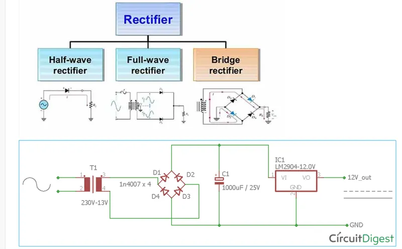
There are three types of power converter circuits used in EVs and HEVs are given below
1 AC to DC (rectifier)
2. DC to AC (inverter)
3. DC to DC (chopper)
1. AC to AC (Rectifier):-
An electrical device that converts an alternating current into a direct one by only allowing a current to flow through it in one direction.
user:-
- A boost converter changes the battery in Electric vehicles(EV). A conventional OBC (onboard charging system) has a bridge rectifier to convert the input AC voltage to DC but, during the rectification process, there is high conduction, and switching losses and heating issues are also attached to it.
- Rectifiers have many users but are often found serving as a component of DC power supplies and high -voltage direct -current power transaction systems.
- Rectification may serve in roles other than generating direct current for use as a source of power.
- As noted, detection of radio signal serves as a rectifier
- in a gas heating system flames rectification is used to directly detect the presence of a flame
2. DC to AC converter:-
- A dc to dc converter is a power electrics device that accepts a DC input voltage and an Ac output voltage
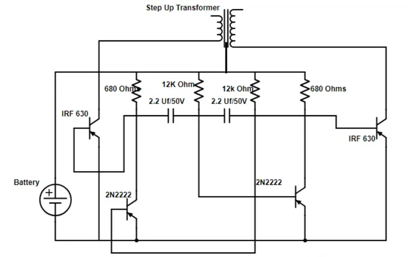
- An inverter is a device that converts DC power from the battery to AC power used in an electric vehicle motor. The inverter can change the speed at which the motor rotates by adjusting the frequency of alternating current
3. DC to DC converter;-
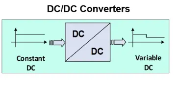
- A dc-dc converter is a power electronic device that accepts a DC input And output also DC voltage
- The output voltage of the DC to DC converter can be greater than the input voltage or vice versa. the converter output voltage is used to match the power supply required to the loads
Q.
2. An Electric Vehicle's powertrain with a 72V battery pack is shown in the diagram below. The duty ratio for acceleration operation is 'd1' and for the braking operation the duty ratio is 'd2'.
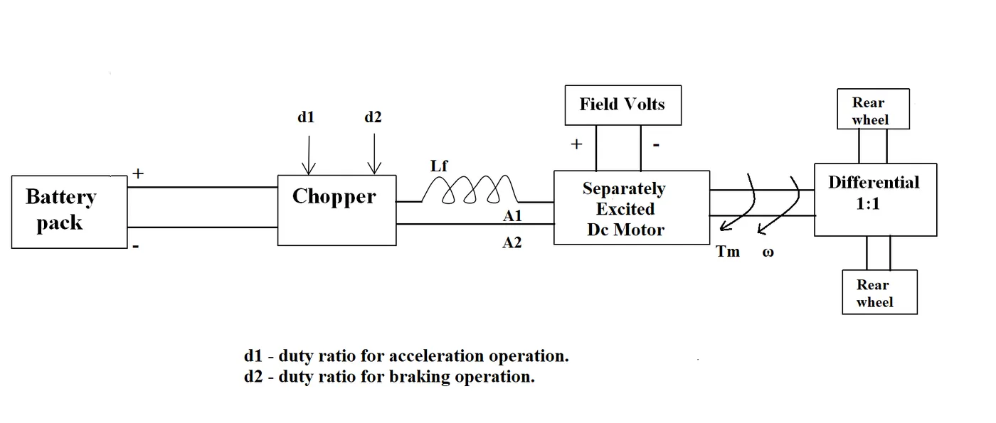
The other parameters of the electric vehicle are given below,
Motor and Controller Parameters:
Rated Armature voltage= 72 V
Rated armature current= 400 A
Ra= 0.5Ω, KΦ= 0.7 Volt second
Chopper Switching frequency= 400 Hz
The vehicle speed-torque characteristics are given by the below equation

What is EV steady-state speed if the duty cycle is 70%?
Ans:-
- As the torque formula is given, we need to find the speed in rad/sec. use the other expression available which is given below.
T=v.k/R -k^2.w/R
- Rated voltage =70v
- Duty cycle=70%
- so supplied voltage for the combinedmotion =70/100*70=50.4v
- torque euation ,T=(v_t*k_phi)/(R_a)-(w_m.((k_phi)^2)/R_a)
- substituting value
- T=(50.4*0.7)/(0.5)-(w*((0.7)^2)/0.5)-----(1) equation
- At stesdy state condition
- equation (1)=24.7+(0.0051)*W^2
- 70.56-0.98w=24.7+0.0051w^2
CACULATION ( TORQUE euation of motor);-.
Torque,T=(V*kQ)/Ra-(w/Ra)*(kQ)^2---------(1)
where ,v=supply voltage ,Ra=armature resistance
w=Speed of motor in rad/sec
kQ=Speed constant of motor subsutituting in equation in (1) v=50.4v,Ra=0.50ohms,kQ=0.7
T=(50.4*0.7)/0.5-(0.7)^2*(w/0.5)
T=70.56-0.98w---------(2) equ.
T=24.7+0.0051w^2--------(3) equ.
equ (2) and(3)
70.56-0.98w=24.7+0.0051w^2 By rearranging,
0.0051w^2+0.98w-45.86=0------(4)
solving (4),we get w=38.91,-231.0.7
Since the drive is in motoring mode we can take speed as position .w=38.91rad/s
3. Develop a mathematical model of a DC Motor for the below equation using Simulink.
ωω= V/Kϕϕ -Ra/Kϕϕ^2 .T
Ans:-
given equation :-
w=v/kQ -Ra/kQ^2.T
model of Simulink:-
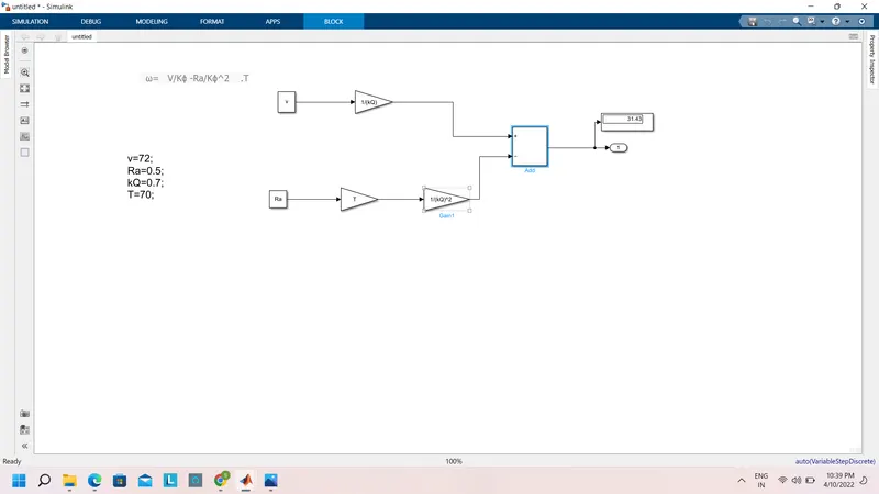
value of parameter _
v=72v
Ra=0.5ohm
kQ=0.7v
T=70
output of value is 31.43
******************************************************************************************
Q.4
4. Refer to the blog on the below topic:
Induction Versus DC brushless motors by Wally Rippel, Tesla
Explain in brief the author’s perspective.
solution:-
according to the blog 'indication' Vs DC Brushless motor by Wally Rippel, Tesla, the writer states the change in the world years ago and the latest technology trends that are happing. He then explains the DC brushless motor and induction motor
DC Brushless Machines:-
According to him, the rotor has two or more permanent magnets that generate a DC magnetic field .this magnetic field will enter the stator core which interacts with the current flowing in the winding to produce an interaction between the rotor and stator /it needs a proper flow of current into the rotor and stator if it's not connected properly the current will not generator. the magnitude and polarity of the stator current will continuously vary such that torque remains constant and optimal efficiency is achieved.
Induction motor:-
The 3-phase induction motor was invented by Nikola Tesla sometime before 1889. The stars of the 3-phase induction motor and the DC brushless motor are virtually identical. Both have their sets of distributed winding that are inserted within the stator core. The essential difference between the two machines is the rotor.
The induced currents in the rotor windings in turn create magnetic fields in the rotor that react against the stator field. The direction of the magnetic field created will be such as to oppose the change in current through the rotor windings, in agreement with LENs law. The cause of induced current in the rotor windings is the rotating stator magnetic field, so to oppose the change in rotor-winding currents the rotor will start to rotate in the direction of the rotating stator magnetic field. The rotor accelerates until the magnitude of induced rotor current and torque balances the applied mechanical load on the rotation of the rotor. Since rotation at synchronous speed would result in no induced rotor current, an induction motor always operates slightly slower than synchronous speed. The difference, or "slip," between actual and synchronous speed varies from about 0.5% to 5.0% for standard Design B torque curve induction motors. The induction motor's essential character is that it is created solely by induction instead of being separately excited as in synchronous or DC machines or being self-magnetized as in a permanent magnetic motor