Week-6 Challenge: EV Drivetrain
1. Which types of power converter circuits are employed in electric and hybrid electric vehicle?
A: Electronics applied for the conversion and control of electric power is called Power electronics. These Power electronics components used in electric vehicle and hybrid electric vehicle are known as Power coonverters. These power converters operates with semiconductor switching technology and have high efficiency.
Power converters used in EV and HEV:
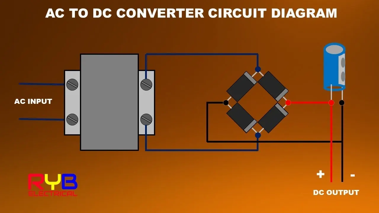
- AC to DC Converters: It is basically a device that converts AC voltage into DC voltage. These converters are also called as Rectifier circuits. The process of conversion is called rectification. There are many applications which require the conversion of AC voltage supply to DC voltage supply. Step down transformers are used to decrease the voltage level and step up transformers are used to increase the voltage level. The rectifiers used for converting AC voltage to DC voltage can be half wave rectifier, full wave rectifier and bridge rectifier. eg: Consider a mobile charger circuit in which it takes the input AC supply and converts it into DC supply which is stored in the battery of phone.
- DC to AC Converters: DC to AC voltage converters are called as Inverters. They convert constant voltage and power from one dc level to other voltage and frequency ac level. They are used in power electronic applications where the power input pure 12V, 24V, 48V DC voltage that requires power conversion for an AC output with a certain frequency. These are used in numerous applications, including PV systems, battery storage systems, traction drives, variable speed drives, etc. Converting from DC to AC is more complicated because the circuit needs some kind of oscillator that reverses the current direction at the required frequency. Most inverters rely on resistors, capacitors, transistors, and other circuit devices for converting DC Voltage to AC Voltage. eg: to run an induction motor from a battery.
- AC to AC Converters: AC to AC converters is used for converting the AC waveforms with one particular frequency and magnitude to AC waveform with another frequency at another magnitude. This conversion is mainly required in case of speed controlling of machines, for low frequency and variable voltage magnitude applications as well.
The AC to AC converters can be classified into different types:
- Cycloconverters:They are majorly called as frequency changers that convert the AC power with one input frequency to AC power with a different output frequency.
- AC to AC Converters with DC link:AC to AC converters with a DC link generally consists of a rectifier, DC link, and inverter as in this process the AC is converted into DC in rectifier. After being converted into DC, the DC link is used to store DC power, and then again it is converted into AC by using the inverter.
- Matrix Converters:Matrix converters are used for converting AC to AC directly without using any DC link for increasing the reliability and efficiency of the system by reducing the cost and losses of the DC-link storage element.
- Hybrid Matrix Converters:The matrix converters that convert AC/DC/AC are termed as , and similar to the matrix converters, these hybrid converters also don’t use any capacitor or inductor or DC link.
- DC to DC Converters: A DC-to-DC converter is an electronic circuit or electromechanical device that converts a source of DC from one voltage level to another. It is a type of electric power converter. Power levels range from very low (small batteries) to very high (high-voltage power transmission).
Classification of dc to dc converters are:
- Boost bidirectional DC-to-DC converter
- Buck bidirectional DC-to-DC converter
- Boost-buck non-inverting bidirectional DC-to-DC converter
- Boost-buck inverting bidirectional DC-to-DC converter
- SEPIC bidirectional DC-to-DC converter
- CUK bidirectional DC-to-DC converter
2.An Electric Vehicle's powertrain with 72V battery pack in shown in the diagram below. The duty ratio for acceleration operation is 'd1' and for the braking operation the duty ratio is 'd2'.
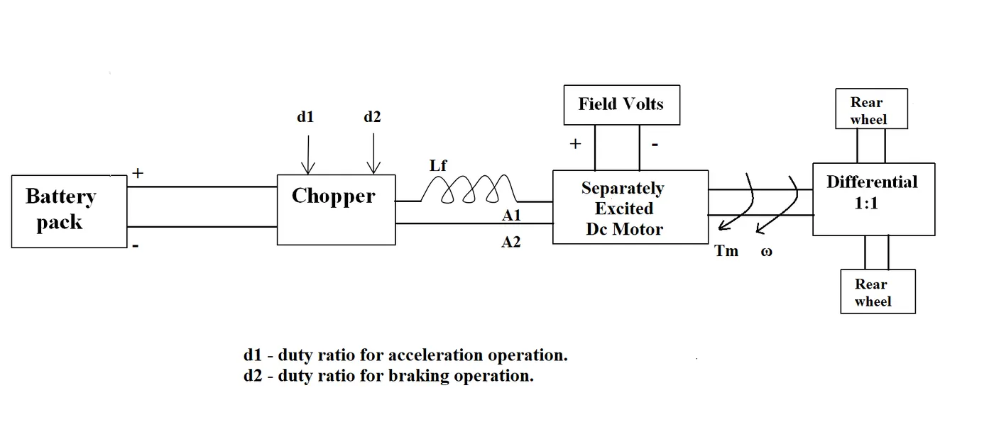
The other parameters of the electric vehicle is given below:
Motor and Controller Parameters:
- Rated Armature voltage= 72 V
- Rated armature current= 400 A
- Ra= 0.5Ω, KΦ= 0.7 Volt second
- Chopper Switching frequency= 400 Hz
The vehicle speed-torque characteristics are given by the below equation;

What is EV steady state speed if duty cycle is 70%?
A: Given datas are;
- Rated Armature voltage= 72 V
- Rated armature current= 400 A
- Ra= 0.5Ω, KΦ= 0.7 Volt second
- Chopper Switching frequency= 400 Hz
- Duty cycle = 70% = 0.70
Given that vehicle torque (Nm);
................(1)
We know the torque equation for vehicle torque Tv = (Vv*KΦ/Ra)-((ω*KΦ^2)/Ra)
We also know that duty cycle D = Vout/Vin
Vehicle output Vv is given by; Vv=D*Vin
Vv= 72*0.7 = 50.4V
So Tv = ((50.4*0.7)/0.5)-(0.98ω)
Tv = 70.56 - 0.98ω .................(2)
Solving equation (1) and (2);
24.7 + 0.0051ω^2= 70.56 - 0.98ω
We get a quadratic equation;
0.0051ω^2 + 0.98ω - 46.94=0
The roots of quadratic equation are 38.85 rad/s and -230.95 rad/s.
The value of ω is taken as the positive value 38.85 rad/s.
RESULT :
EV steadystate speed at duty cycle of 70% is 38.85 rad/s.
3. Develop a mathematical model of a DC Motor for the below equation using Simulink.
ω= V/Kϕ -Ra/Kϕ^2 *T
A: Mathematical model of dc motor is developed using angular velocity equation. (speed -torque equation)
- ω= V/Kϕ -Ra/Kϕ^2 *T
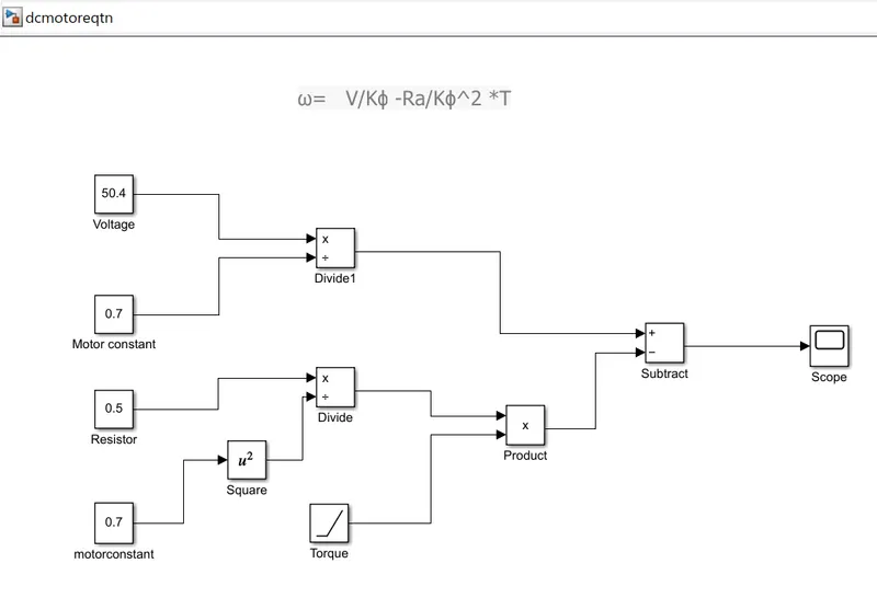
- Inorder to make a Simulink model from an equation we need to add different math function blocks and give corresponding input values as well.
- Here all the variables are assigned values as same as to question 2.
- Simulation time is set to 100 s.
- Vehicle voltage = 50.4v, motor constant kΦ = 0.7, Ra= 0.5 ohm.
- Blocks used for modeling are : Constant block, ramp block, divide block, subtract block, product block, square block and scope.
Simulink Model:
OUTPUT:
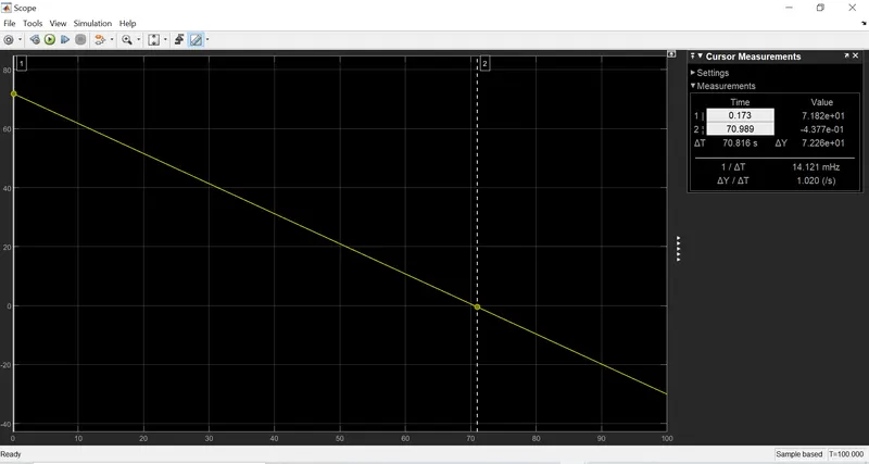
RESULT:
Speed torque characteristics of dc motor is obtained as a result of modeling the given equation. It is observed that starting torque is 70.81 Nm and it goes to zero as speed approaches to 70.98 rpm.
https://drive.google.com/file/d/1DDCTZDOBMpzXp0MExPUpCEuKRXlVg5P3/view?usp=sharing
4. Refer to the blog on below topic: Induction Versus DC brushless motors by Wally Rippel, Tesla
Explain in brief about author’s perspective.
A: In the blog by Wally Rippel, the author has mentioned the growth and development in dc brushless and induction drive in the automobile industry. He have explained the details regarding the construction, working, advantages, performance efficiencies, applications of induction motor drives and dc brushless motor drives.
For DC Brushless motor drives its construction implements 2 or more permenant magnets at the rotor to generate a dc magnetic field. It consists of a stator core made up of thin, stacked laminations. It uses an inverter for current control as the current direction has to be changed repeatedly to maintain a constant torque.
In case of induction motor the current is supplied to the stator which results in the generation of emf. This emf comes in contact with the rotor which is generally a squirrel cage type and results in current induced in the rotor. Here the rotor has no magnets but instead are stacked steel laminations with buried peripheral conductors which form a shorted structure.
Induction motors doesnot require an inverter to start the drive and the starting torque whereas brushless dc drive without an inverter is said to be a waste.
DC brushless drives require permanent magnets and cannot vary thier magnetic field strength. The permenant magnets used are expensive ie, $50 per kilogram and thier magnetic field are difficult to control if ferromagnetic material gets close enough to the field. But less rotor heat is produced and rotor cooling is easier.
If used with a smart inverter Induction motor drives can be operated with minimum hysteresis and eddy current losses and maximum efficiency as magnetic field strength can be varied according to the rotor requirement.
As the size of brushless dc drive increases the losses also increases and efficiency decreases but for induction drives the losses and efficiency doesnot increases as the size of drive increases. So induction drives have a cost advantage compared to brushless dc drives.
DC brushless drives can operate at unity powerfactor 1, whereas induction drives can operate only upto a powerfactor of 85%.
In conclusion the author has elaborated various aspects to compare induction drives anf DC brushless drives and presented detailed advantages and disadvantages of both. He have also mentioned that there is no best type. At the end it depends on preference of user. If the user requires high performance with low cost then induction drive will be better option whereas if the peak point efficiency, powerfactor and easy controls are the factors considered then selecting a brushless dc drive is better option. Author believes that due to increasing performance of vehicles both the drives will be used side by side. So that he ends the blog by stating there is still no winner.