Week-6 Challenge: EV Drivetrain
1. Which types of power converter circuits are employed in electric and hybrid electric vehicle?
Answer:-
There are 4 main categories of power converter circuits which are used in electric and hybrid electric vehicles. They are listed and elaborated upon below:
AC to DC converter:-
This type of converter takes an AC power supply and converts it to a DC one. Power generated from a power plant is transmitted to our homes at a voltage of 230V at a frequency of 50Hz which we can use to power our electrical appliances. But our appliances operate on a DC supply, not an AC one and so we need a converter for this application. Examples of Ac to DC converters are: phone charger, laptop. charger etc. An AC power supply has an alternating waveform which repeatedly reverses direction. An AC to DC converter will prevent the current changing direction, so that it only flows unidirectional. In the circuit of an AC to DC converter, there is a step down transformer, a diode, a capacitor and a low dropout voltage (LDO) regulator.
The step down transformer takes the high level 230V from the mains supply and steps it down to a lower level e.g. 12 or 13V for our use, but it is still in AC form. Then, a diode or group of diodes is implemented to restrict the current to flow in just one direction. In an AC waveform, there will be positive and negative peaks at each half cycle like a sine wave. The diode(s) will remove the negative parts of the waveform so that there are positive peaks only. This is called 'rectifying' and this part of the circuit is referred to as a 'rectifier. This can be a half wave, full wave or a bridge rectifier. Then, the rectified output voltage waveform is smothered by a filter capacitor. Finally, the LDO regulator will regulate the output for our use.
In the case of EVS or HEVS, the battery pack which operates with a DC power supply is charged at home or at a charging station both of which are supplied power in AC form from the electric grid. So, the chargers for these vehicles are an example of the AC to DC power converter.
DC to AC converter:-
This type of converter takes a DC supply and converts it to an AC one. Power which is supplied from a battery or capacitor can have its form changed to the AC type for use in homes or systems which have an AC load. For instance, the power generated by solar panels are stored in batteries in the DC form and this can power a house which uses an AC power supply so that we can utilize this power from the mains. This type of converter is referred to as an 'inverter' and is widely used in homes and in EV/HEVs.
The DC supply is changed to an AC waveform using an electronic switch, which is basically a set of semiconductor transistors e.g. IGBTs. MOSFETS. These switches are controlled by a controller to either be in an open or closed position to direct the flow of current in a circuit. The controller sends signals to the switches to tell it to open/close, and even decides the frequency for the same. By doing this operation, the DC current mimics an AC current and can be fed to the load which requires it.
In the case of EVS and HEVS, the battery pack will supply its power the inverter. The inverter contains a transformer which consists of a primary and secondary winding. The current from the battery is first supplied to the primary winding where the electronic switches will repeatedly reverse the direction of the current to create an AC waveform. This current will return back the way it came from. The AC current in the primary winding will induce an AC current in the secondary winding which then supplies this current to an AC load e.g. the AC traction motor.
DC to DC converter:-
This type of converter is similar to a transformer in that it can change the voltage from its current level to another level. It can take an input supply of voltage and increase it or do the exact opposite and decrease it similar to a step up or step down transfomer. This kind of a converter is called a 'chopper. The purpose of using this type of converter is to provide the necessary level of power to a particular component and for the safety of the appliance and the user. If a component if suppled with too little or too much voltage, it won't operate due to lack of power or it will get damaged, so it all depends on the load requirement.
It works by taking the DC supply and passing it through a switching element which converts the waveform to a square wave which is actually AC in nature. Then this AC is passed through a filter which will will turn it back in to a DC supply for use in a load. In EVS, HEVs and conventional vehicles, this type of converter is used for various purposes. E.g. In the case of stepping down the voltage, the car radio may require a stepped down voltage of 12V to operate and would not need the full voltage of the car battery. In the case of stepping up the voltage, the motor of a car may require 500V to operate, but the vehicle may need more voltage than the battery pack can provide.
There are 2 main types of DC to DC converters which are isolated and non-isolated type. The non-isolated type can be subdivided to 5 types:
1)Buck-to step down the voltage
2)Boost-to step up the voltage
3)Buck/Boost - this can do both step up and step down operations but is mainly used to reverse polarity
4)Cuk-similar to the Buck/Boost type
5)Charge Pump - to step up/step down the voltage for low power sources
The isolated type can be subdivided in to 2 types:
1)Flyback converter - similar to the Buck Boost converter except it uses a transformer instead of an inductor to store energy
2)Forward converter - this type will use a transformer to send energy between the input and output in a single step.
AC to AC converter:-
This type of converter takes an input AC waveform with a particular voltage and frequency and outputs a different AC waveform with another voltage and frequency. The output voltage and/or frequency can be changed or maintained depending on the application. This converter has many applications in our daily life e.g. lamp dimming, motor speed control. There are 4 main types of AC to AC converters
Cycloconverters:-
This type is also known as a frequency changer as it will change the frequency of an input AC waveform and output an AC waveform with another frequency but it can also change the magnitude of the power. This type of converter does not have any DC linkages and avoids any conversion between AC and DC to prevent losses and save costs. The input wave's frequency is changed by changing the firing angle applied to a thyristor. By switching the positive and negative limb thyristors, we can get an output waveform that has a stepped up/down frequency compared to the input.
AC to AC convert with DC Link:-
As the name suggests, this type includes a DC link along with a rectifier and an inverter. The input AC waveform is first rectified by the rectifier to remove the negative portions of the AC wave and output only the positive portions. This creates a DC waveform which is then stored in the DC link and is then converted back to an AC waveform using the inverter.
Matrix Converter:-
This type converts from AC to AC directly without using a DC linkage to reduce costs and losses that would otherwise be incurred with a DC link storage element. It is used mainly to increase the reliability and efficiency of a system. Matrix converters use bidirectional switches (IGBTS) to conduct current and block voltages of both polarities.
Hybrid Matrix Converter:-
This type is very similar to the matrix converter in that they combine the AC//DC/AC design with the matrix design it uses unidirectional switches and 2 converter stages, without the DC link to reduce the size and weight of the converter.
-----------------------------------------------------------------------------------------------------------------------------
2. An Electric Vehicle's powertrain with 72V battery pack in shown in the diagram below. The duty ratio for acceleration operation is 'd1' and for the braking operation the duty ratio is 'd2'.
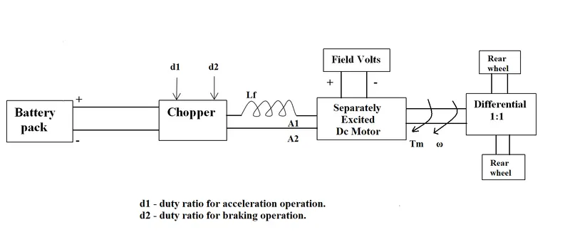
The other parameters of the electric vehicle is given below,
Motor and Controller Parameters:
Rated Armature voltage= 72 V
Rated armature current= 400 A
Ra= 0.5Ω, KΦ= 0.7 Volt second
Chopper Switching frequency= 400 Hz
The vehicle speed-torque characteristics are given by the below equation

What is EV steady state speed if duty cycle is 70%?
Answer:-
Duty Cycle = 70% = 0.7
Voltage (V) = Rated Armature Voltage * Duty cycle
Voltage (V) = 50.4 Volt
As we know Torque_Speed Characteristics of DC motor is
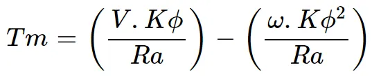 `omega`
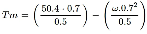
Tm=70.56-0.98*w...............eqn (1)
Given that
Tv=24.7+(0.0051)*w^2.............eqn (2)
Comparing both equation
Tm=Tv
| 70.56-0.98*w=24.7+(0.0051)*w^2...... fill the value |
0.0051w^2 = 0.98w-70.56-24.7
0.0051w^2 = 0.98w-45.86 = 0........eqn (3) Its quadratic equation
formula for quadratic equation =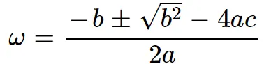
then we get, W = 38.9150 and W = -231.071
so steady state speed of EV is 38.9150 rad/sec
------------------------------------------------------------------------------------------------------
3. Develop a mathematical model of a DC Motor for the below equation using Simulink.

Answer:-
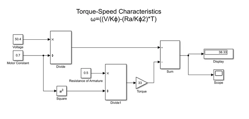
Given =
Voltage (V) = 50.4 volt
Motor Constant (Kϕ) = 0.7 volt-sec
Resistance of armature (Ra) = 0.5 ohms
Torque (T) = 33
Angular speed (W) = 38.33 rad/sec
----------------------------------------------------------------------------------------------------
4. Refer to the blog on below topic:
Induction Versus DC brushless motors by Wally Rippel, Tesla
Explain in brief about author’s perspective.
Answer:-
Whally Rippel says that the he is seen lot of changes in the electric vehicle industries right from when he was young and when they used to use lead acid batteries and dc motor to now where most vehicles use lithium polymer cells and brushless dc motor or induction motor. He states that the two most commonly used motors are three phase induction motor and a brushless dc motor also called BLDC motor.
He also states that just like different typed of engine are suited to different appln then simillarly the motor in an electric vehicle are also of different type. The choice between an induction and BLDC motor depends purely on the applicaton and cost. For instance he describes how both motor works and by far the induction motor is more complex to design and understand as it has more components such an inverters that need feedback loops. But the induction motor if ideally designed can produced a large amount of torque for the provide load al,ost right from the start.
he also states about the construction of the motors where both have the same stator but they differ in the construction of the rotor. He talks about how hybrid electric vehicles adopts these motor based on their requirements and states that it BLDC motor is commonly used where as only pure electric like tesla roadster make the use of induction motor. In the end he claims its not possible to conclude which of two is best.