Week - 4
AIM:
#1.Implement control logic of a “washing machine” using Stateflow as per given sequence:
THEORY-
A washing machine is a machine that washes dirty clothes. It contains a barrel. into which the clothes are placed. This barrel is filled with water, and then rotated very quickly to make the water remove dirt from the clothes. Most washing machines are made so that detergents (liquids or powders) can be put into the machine. These can help make the clothes cleaner.
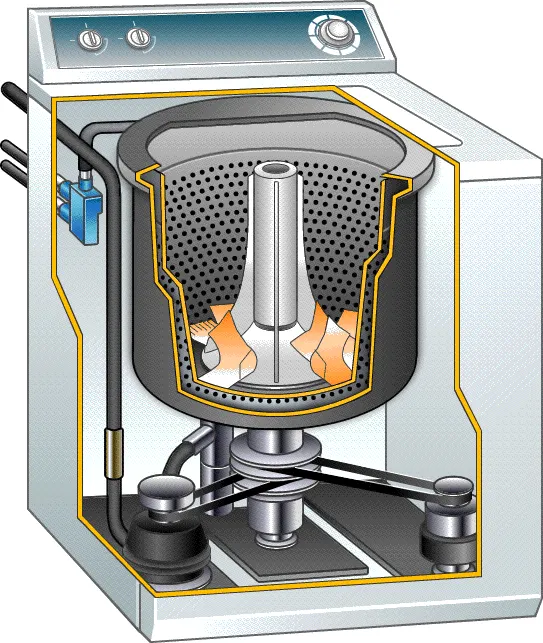
Step of washing machine:
1. Soaking
2. Washing
3. Rinsing
4. Drying
Conditions:
- If power is ON, the system should be activated.
- The process should taken place when water supply is available or else stop the process with indicating LED.
- Soaking time is 200 seconds.
- Washing time is seconds.
- Rinsing time is 20 seconds.
- Drying time is for 50 seconds.
- After completion of all process finished LED should glow.
Block used:
i) Chart-
A finite state machine is a representation of an event-driven (reactive) system. In an event-driven system, the system responds to an event by making a transition from one state (mode) to another. This transition occurs if the condition defining the change is true.
ii)Display-
The Display block shows the value of the input data. You can specify the frequency of the display. For numeric input data, you can also specify the format of the display.
iii)Constant-
The Constant block generates a real or complex constant value signal. Use this block to provide a constant signal input.
iv)Lamp-

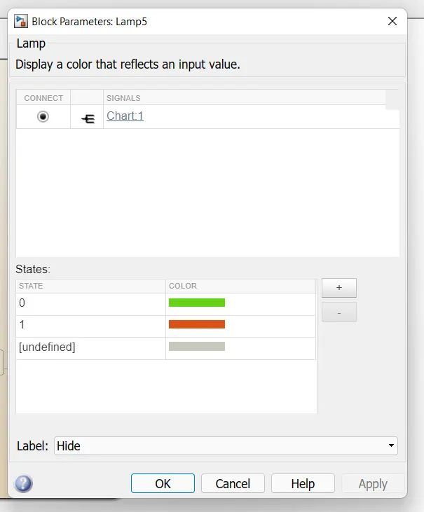
The Lamp block displays a color indicating the value of the input signal. You can use the Lamp block with other Dashboard blocks to build an interactive dashboard of controls and indicators for your model. You can specify pairs of input values and colors to provide the information you want during the simulation.
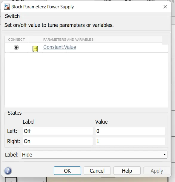
v)Switch-
The Slider Switch block toggles the value of the connected block parameter between two values during simulation. For example, you can connect the Slider Switch block to a Switch block in your model and change its state during simulation. Use the Slider Switch block with other Dashboard blocks to create an interactive dashboard for your model.
Double-clicking the Slider Switch block does not open its dialog box during simulation and when the block is selected. To edit the block's parameters, you can use the Property Inspector, or you can right-click the block and select Block Parameters from the context menu.
Block used inside chart-
Description:
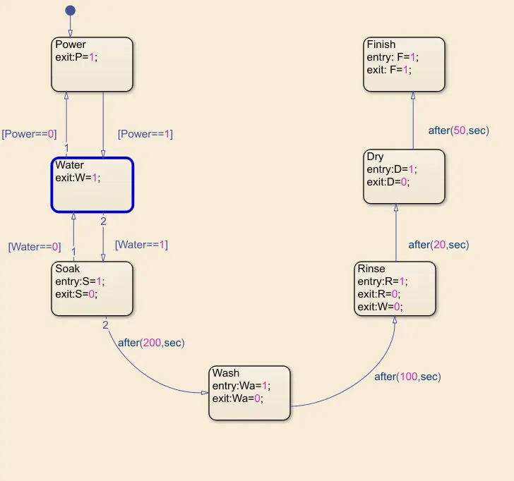
1. Power and Switch inputs were controlled by the Switch block. These two inputs were directed to the Chart block. 2. State blocks were used inside charts to create a stateflow according to the given criteria.
3. The POWER input is get as input in the chart and directed to the POWER State from there, if Power-=1(Which is power supply in ON), it is directed to the next WATER block. or if Power=-0 (Power supply is OFF), it directed to the junction.
4. Next state is WATER and from that if Water=-1(Water supply is ON) it moves to the next stage or if Water =0(Water supply is OFF) then it is directed to the junction.
5. Next to water is SOAKING state, entry is given as O, while exit is LED is made to glow which is connected to this state.
6. After 200 sec, it is directed to Washing state, and after 100sec it is directed to Rinsing state and after 20sec, to Drying state and after 50sec, it is ended to End state.
SYMBOL PANE-
Here,
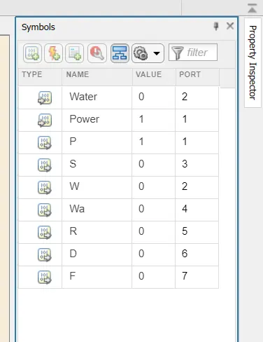
Power Supply & water supply is as input given while all other like Washing_State, D(dryer), Wa(washing), S(soaking), R(Ririnsing), Washing Completed are all output given.
Complete Simulink Model-
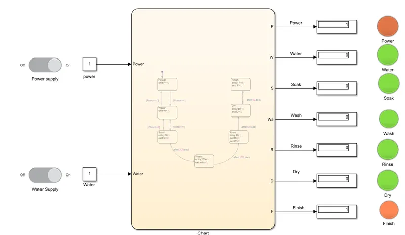
i)At the time of starting(If the power supply is available, the system gets activated)-
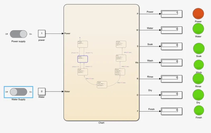
ii)If the Water supply is not available, stop the process & indicate through LED-
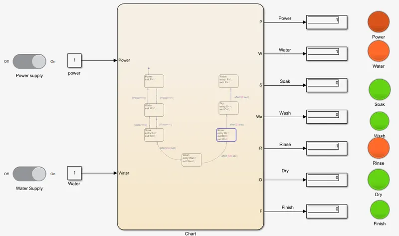
iii)simulink model showing that the washing process is completed and rinsing is going on-
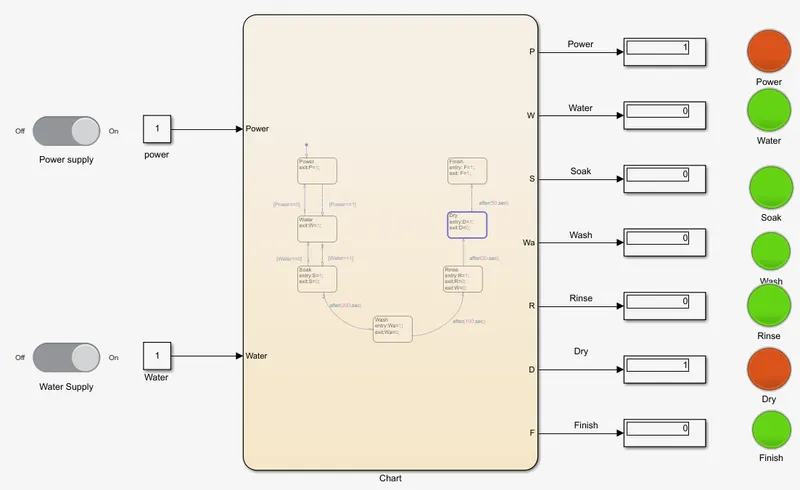
iv)simulink model showing that the rinsing process is completed and drying is going on-
#2. Make a Simulink chart for the “Gear shift” logic as per below conditions:
Speed Range(kmph) Gear
0 to 15 1
16 to 25 2
26 to 40 3
41 to 60 4
Above 61 5
Give speed input while the simulation is running & display the gear number.
Solution:
Theory:
The basic rule is that you change up through the gears as the speed of the car increases and down when you need more power from the engine. For example, you would change down to a lower gear when climbing a hill or pulling away at low speed.
The gears determine the amount of power available from the engine. First gear provides the most pulling power but the least potential for speed, whilst fifth gear which provides the least pulling power allows the greatest range of speed. The following table indicates typical speed and revs for changing gears up or down.
Block used:
i) Chart-
A finite state machine is a representation of an event-driven (reactive) system. In an event-driven system, the system responds to an event by making a transition from one state (mode) to another. This transition occurs if the condition defining the change is true.
ii)Display-
The Display block shows the value of the input data. You can specify the frequency of the display. For numeric input data, you can also specify the format of the display.
iii)Signal Builder-
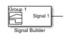
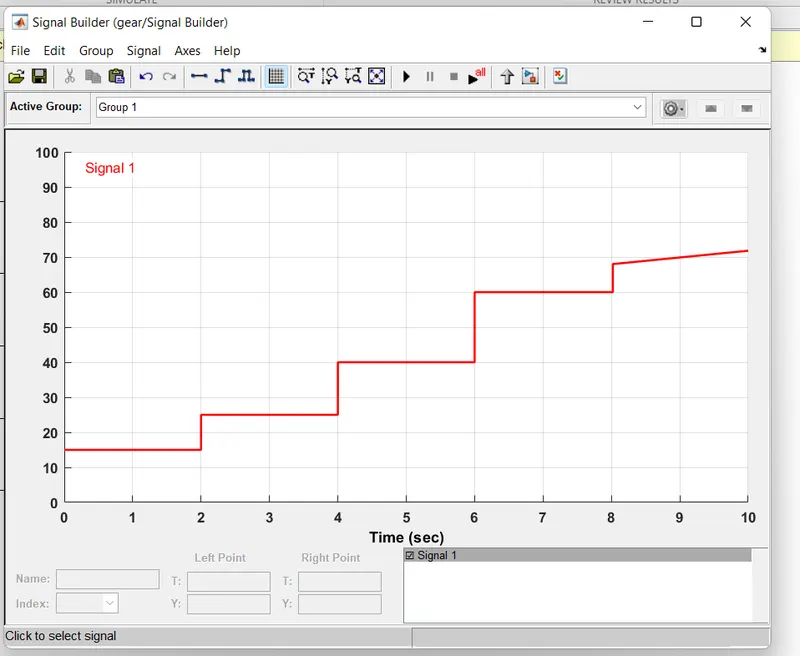
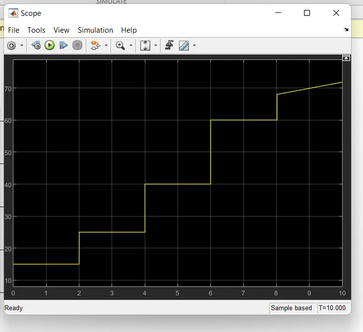
The Signal Builder block allows you to create interchangeable groups of piecewise linear signal sources and use them in a model. You can quickly switch the signal groups into and out of a model to facilitate testing. In the Signal Builder window, create signals and define the output waveforms.To open the window, double-click the block.
iv)Lamp-
The Lamp block displays a color indicating the value of the input signal. You can use the Lamp block with other Dashboard blocks to build an interactive dashboard of controls and indicators for your model. You can specify pairs of input values and colors to provide the information you want during the simulation.
Stateflow Chart Description:
1. By giving a input through signal builder block the inputs are varied by the user during the run-time and it is connected to the chart block This varying input values were given to the chart from signal builder blocks.
2. State blocks were used inside the chart to get a conditioned state flow.
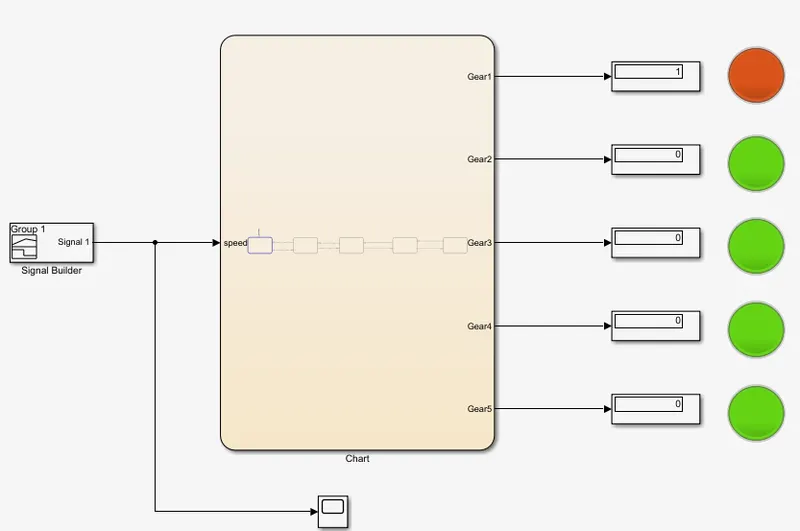
3. First the input values are generated to the GEAR SHIFT block, from there according to the condition, When range of the speed between 0- 15kmph then Gear-1works. and satisfied the condition as per given.
4. When Gear-1 it moves to the Gear-2 state and the input value crosses 15kmph, it moves to the next state. Like if speed goes to 25kmph it moves to the next state or it will be back to the first state.
5. When Gear-2 it moves to the Gear-3 state and the input value crosses 40kmph, it moves to the next state. Like if speed goes to 40kmph it moves to the next state or it will be back to the first state and vice-versa.
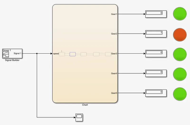
6. A Display block is connected with each gear output to get the value of 0 or 1, which denotes whether the gear is in active state and according to this lamp glows on and off.
7. Stop Time is given as inf as simulation goes on until the user pauses or ends the simulation.
1st Gear-
2nd Gear-
As speed input is above 15 kmph, it shifts to the second gear and lamp for second gear is on and first gear lamp goes off.
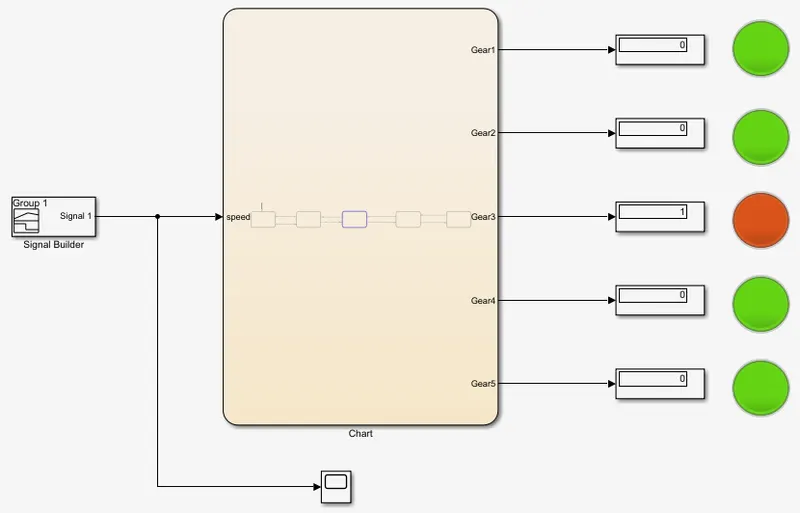
3rd Gear-
As speed input is above 25kmph, it shifts to the third gear and lamp for third gear is on and second gear lamp goes off.
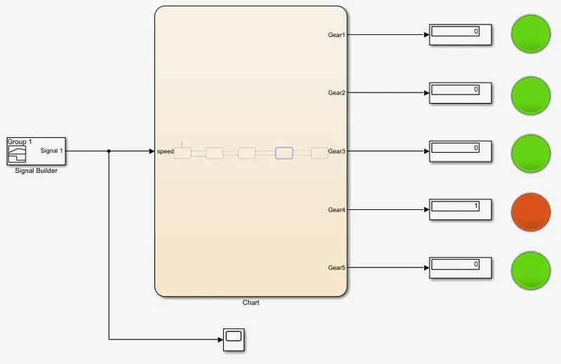
4th Gear-
As speed input is above 40kmph, it shifts to the fourth gear and lamp for fourth gear is on and third gear lamp goes off.
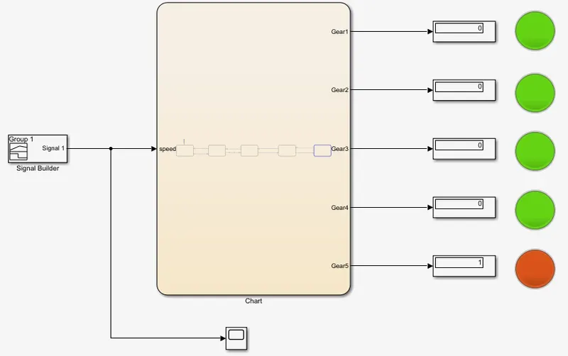
5th Gear-
As speed input is increase more than 60kmph, it shift to fifth gear.
LEARNING OUTCOME:
The working of Slider switch block, Lamp block and learnt the working of stateflow for the given condition.
RESULTS AND CONCLUSION:
A control logic of a "washing machine using Stateflow for the given sequence is implemented and A Simulink chart for the "Gear shift" logic for the given conditions is made.