Week-6 Challenge: EV Drivetrain
1. Which types of power converter circuits are employed in electric and hybrid electric vehicle?
ans)
here 4 types of power converter circuits that are used in electric and hybrid electric vehicles.
1. AC to DC converter:
The electrical circuits that transform alternating current (AC) input into direct current (DC) output are known as AC-DC converters. They are used in power electronic applications where the power input is a 50 Hz or 60 Hz sine-wave AC voltage that requires power conversion for a DC output.
This converter is known as Rectifier.
The AC to DC Converters is used in almost all electronics and electrical devices. They are used as power supply circuits for Household applications like vacuum cleaners, washing machines, refrigerators, electric rice cookers.
For EVs and HEVs, the battery pack which operates with a DC power supply is charged at home or at a charging station both of which are supplied power in AC form from the electric grid. So, the chargers for these vehicles are an example of the AC to DC power conveter.
2. DC to AC converter:
The DC to AC converters is used in a vehicle to charge their batteries. These circuits are mainly used for driving low-power AC motors and are used in a solar power system. Thus, this is all about DC to AC converter. These can be used in dc transmission lines for transmitting power to loads. This converter is also known as an inverter.
DC to AC Converter The common inverter technology used in electronics is to convert a voltage source from a battery into an AC signal. Generally, they operate with 12 volts and are commonly used in applications like automotive, lead-acid technology, photovoltaic cells, etc. The DC to AC converters is used in a vehicle to charge their batteries. These circuits are mainly used for driving low-power AC motors and are used in a solar power system. Thus, this is all about DC to AC converter.
For EVs and HEVs, the battery pack will supply its power to the inverter. The inverter contains a transformer that consists of a primary and secondary winding. The current from the battery is first supplied to the primary winding where the electronic switches will repeatedly reverse the direction of the current to create an Ac waveform.
3. AC to AC converter:
AC to AC converters is used for converting the AC waveforms with one particular frequency and magnitude to AC waveform with another frequency at another magnitude. This conversion is mainly required in the case of speed controlling of machines, for low frequency and variable voltage magnitude applications as well. To operate a few devices and machines we require some specific voltage with a specific frequency which can be obtained using AC to AC converters. By regulating AC power using the AC to AC converter we can regulate the speed of induction motors. There are different types of AC to AC converters which are classified based on different criteria.
AC to AC converters with a DC link generally consists of a rectifier, DC link, and inverter as in this process the AC is converted into DC by using the rectifier. After being converted into DC, the DC link is used to store DC power, and then again it is converted into AC by using the inverter.
This converter is also known as a regulator.
This converter has many applications in our daily life like motor speed control, lamp dimming, etc.
4. DC to DC converter :
A DC/DC converter is a class of power supply that converts a source of direct current (DC) from one voltage level to another.
DC-to-DC Converters have a variety of applications. DC-to-DC converters are used to reduce High voltage DC input to low voltage DC output for some specific appliances. They are also used to isolate some highly sensitive components in a circuit from other components of the circuit to avoid any kind of damage. DC/DC converters are used for the following reasons: – To step down the voltage from a high voltage source to a lower voltage, – To match the loads to the power supply, – To isolate the primary and secondary circuits It is a type of converter that works very efficiently. It helps to change one level/voltage of DC into another level/voltage of DC.
2. An Electric Vehicle's powertrain with 72V battery pack in shown in the diagram below. The duty ratio for acceleration operation is 'd1' and for the braking operation the duty ratio is 'd2'.
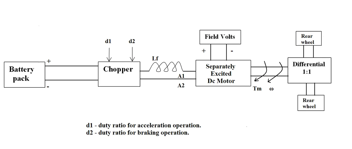
The other parameters of the electric vehicle is given below,
Motor and Controller Parameters:
Rated Armature voltage= 72 V
Rated armature current= 400 A
Ra= 0.5Ω, KΦ= 0.7 Volt second
Chopper Switching frequency= 400 Hz
The vehicle speed-torque characteristics are given by the below equation

What is EV steady state speed if duty cycle is 70%?
ans)
parameters are written below,
V=72v so battery voltage is Vbatt=72*0.7=50.4V
Ia=400A
Ra=0.5Ω
KΦ= 0.7 Volt second
duty cycle d = 70% = 0.7
Now they given equation
Tv = 24.7 + (0.0051)w^2.........(1)
and we know that
w = (Vbatt/KΦ)-(Tv*Ra)/(KΦ)^2
so Tv = Vbatt*KΦ/Ra - w*(KΦ)^2/Ra ........(2)
Now eq(1)=eq(2)
24.7 + (0.0051)w^2 = Vbatt*KΦ/Ra - w*(KΦ)^2/Ra
24.7 + (0.0051)w^2 = 50.4*0.7/0.5 - w*(0.7*0.7)/0.5
0.0051w^2 + 0.98w - 45.86 =0
here we divide upper equation with 0.0051 so we get equation down there
w^2 + 192.156w - 8992.156= 0 ...........(3)
Now this equation (3) is similar to ax^2+bx+c=0.
so here a = 1 , b = 192.156 ,c = -8992.156
x=(-b + (b^2 - 4*a*c)^1/2)/2*a or x=(-b - (b^2 - 4*a*c)^1/2)/2*a
so
w = 38.915 OR w = -231.072
so EV steady state speed if duty cycle is 70% is 38.915 rad/s.
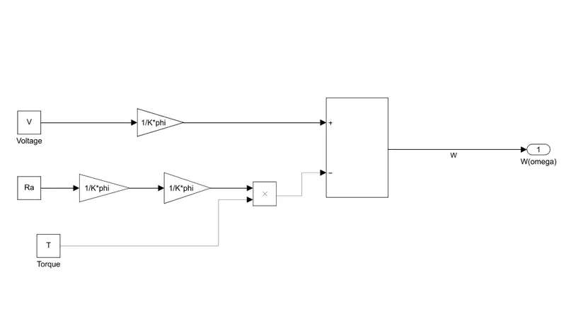
3. Develop a mathematical model of a DC Motor for the below equation using Simulink.
ω = V/Kϕ - Ra/Kϕ^2 .T
ans)
For developing a mathematical model of DC motor for that equation using Simulink we need some blocks to develop a model are given below.
gain
add
product
constants
Now give them a connection as shown below.
4. Refer to the blog on below topic:
Induction Versus DC brushless motors by Wally Rippel, Tesla
Explain in brief about the author’s perspective.
ans)
The author writes this blog to entail the differences between Induction Versus DC brushless motors. here there are many types of motor drives that are used in EVs and other electric applications. So first they tell us about in old days that includes lead-acid batteries, DC brush motors, and contactor controllers. Today, Lead has been replaced by lithium and DC by either DC brushless or induction. Contactors, meanwhile, have given way to modulating inverters.
Then author writes about these technologies and their workings. So first for brushless DC machines, the rotor includes two or more permanent magnets that generate a DC magnetic field. In turn, this magnetic field enters the stator core and interacts with currents flowing within the windings to produce a torque interaction between the rotor and stator. As the rotor rotates, it is necessary that the magnitude and polarity of the stator currents be continuously varied – and in just the right way - such that the torque remains constant and the conversion of electrical to mechanical energy is optimally efficient. The device that provides this current control is called an inverter. Now for the 3-phase Induction motor, the stator will same as DC brushless motor only difference is about the rotor.
Now author writes a comparison between DC brushless motor and induction motor. DC brushless and induction drives use motors having similar stators. Both drives use 3-phase modulating inverters. One of the main differences is that much less rotor heat is generated with the DC brushless drive. Rotor cooling is easier and peak point efficiency is generally higher for this drive. The DC brushless drive can also operate at the unity power factor, whereas the best power factor for the induction drive is about 85 percent. This means that the peak point energy efficiency for a DC brushless drive will typically be a few percentage points higher than for an induction drive. In an ideal brushless drive, the strength of the magnetic field produced by the permanent magnets would be adjustable. When maximum torque is required, especially at low speeds, the magnetic field strength (B) should be maximum – so that inverter and motor currents are maintained at their lowest possible values. This minimizes the I² R (current² resistance) losses and thereby optimizes efficiency. Likewise, when torque levels are low, the B field should be reduced such that eddy and hysteresis losses due to B are also reduced. Ideally, B should be adjusted such that the sum of the eddy, hysteresis, and I² losses is minimized. Unfortunately, there is no easy way of changing B with permanent magnets. In contrast, induction machines have no magnets, and B fields are “adjustable,” since B is proportionate to V/f (voltage to frequency). This means that at light loads the inverter can reduce voltage such that magnetic losses are reduced and efficiency is maximized. Thus, the induction machine when operated with a smart inverter has an advantage over a DC brushless machine – magnetic and conduction losses can be traded such that efficiency is optimized. This advantage becomes increasingly important as performance is increased. With DC brushless, as machine size grows, the magnetic losses increase proportionately and part load efficiency drops. With induction, as machine size grows, losses do not necessarily grow. Thus, induction drives may be the favored approach where high-performance is desired; peak efficiency will be a little less than with DC brushless, but average efficiency may actually be better. Permanent magnets are expensive – something like $50 per kilogram. Permanent magnet (PM) rotors are also difficult to handle due to very large forces that come into play when anything ferromagnetic gets close to them. This means that induction motors will likely retain a cost advantage over PM machines. Also, due to the field weakening capabilities of induction machines, inverter ratings and costs appear to be lower, especially for high-performance drives. Since spinning induction machines produce little or no voltage when de-excited, they are easier to protect. Induction machines are more difficult to control. The control laws are more complex and difficult to understand. Achieving stability over the entire torque-speed range and over temperature is more difficult with induction than with DC brushless. This means added development costs, but likely little or no recurring costs.
The fact that so much of the hardware is common for both drives could mean that we will see induction and DC brushless live and work side by side during the coming golden era of hybrid and electric vehicles.