Week-6 Challenge: EV Drivetrain
Solution 1:- Commercial Electric Vehicles are broadly classified as -
- Battery electric vehicles.
- Hybrid electric vehicles or Fuel cell vehicles.
Overview of DC-DC Converters:
- DC-DC Converters in an Electric Vehicle may be classified as unidirectional or bidirectional converters.
- Unidirectional DC-DC Converters are used in various on-board loads such as sensors, controls, entertainment, utilities and safety equipments. They are also used in DC motor drives and electric traction.
- Bidirectional DC-DC Converters find applications in places where battery charging, regenerative braking and backup power are required. The power flow in a bidirectional converter is usually from low voltage side like battery or supercapacitor to a high voltage end is known as boost operation.
- During regenerative braking, the power flows from high voltage side to the low voltage bus to recharge the battery (buck) mode.
- As a backup power system, the bidirectional DC-DC converter faciitates safe operation of the Vehicle when the engine or the electric drive fails to drive the motor.
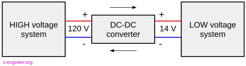
The Converter Topologies are as follows:-
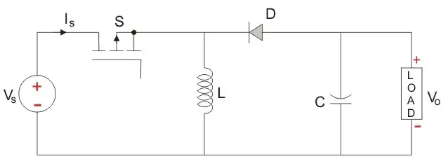
- Buck Converter- The circuit of a buck converter is shown below. It is a step-down converter and gives the average output voltage less than the applied DC input voltage.
2. Boost Converter- The circuit of a boost converter is shown below. It is a step-up converter and the output voltage is always greater than the input voltage.
3. Buck-Boost Converter- The circuit of a buck-boost converter is shown below. The output voltage may be higher or lesser than the input voltage depending the Duty cycle being less than 1 or greater than 1 respectively.
IMPORTANCE OF DC-DC CONVERTERS:-
In electric vehicles which uses a DC Motor, running the motor can use upto three times the voltage provided by the battery. With the help of right converter we can bridge this gap without having to possibly go for a heavy battery.
DC-AC CONVERTERS (INVERTERS)
An inverter is a device that converts DC power from the battery to AC power required by the electric vehicle motor. The inverter can change the speed at which the motor rotates by changing the frequency of the alternating current. A circuit of a 3 phase DC-AC Converter is shown below:-
IMPORTANCE OF DC-AC CONVERTERS:-
- The use of inverters can increase or decrease the power or Torque of the motor by adjusting the amplitude of the signal.
- It plays a significant role in feeding back the power during regenerative braking.
Solution 2:- The motor used in the Electric Vehicle is a seperately excited motor which is being fed from chopper circuit.
In accelerating mode the Chopper circuit will act as a buck converter and hence the motor speed can be derived as a function of time the reduced output voltage, the motor constant, the motor Torque and the armature resistance.
The remaining solution is shown in the images attached below:-
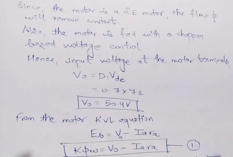
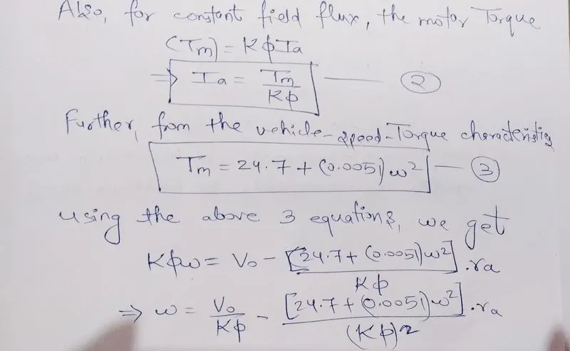
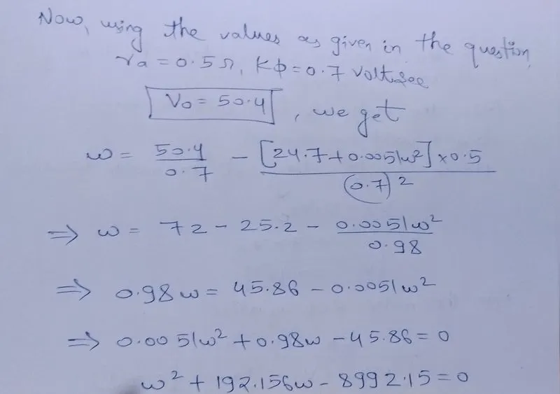
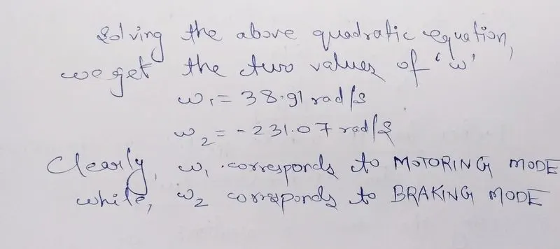
The above explanation can also be seen from the Torque-speed plot for the given vehicle whose MATLAB code is shown below:-
clear all
close all
clc
% given data
V = 72; %rated armature voltage
I = 400; %rated armature current
Ra = 0.5; %armature resistance
K_phi = 0.7; %constant factor
f = 400; %chopper frequency

omega = linspace(0,100,50);
% Speed-Torque characteristics equation
T_v = 24.7 + 0.0051*omega.^2;
V = 72*0.7;
T_m = 70.56 - 0.98*omega;
omega = (V/K_phi)- ((Ra*T_m)/K_phi);

%plotting the result
plot(omega, T_v)
hold on
plot(omega,T_m)
axis([30 80 0 80])
xlabel('Speed(rad/s)')
ylabel('Torque(N-m)')
On executing the above code the following plots are obtained:-
Solution 3:- The Simulink model has been attached seperately in the file "Speed_torque_model" and also shown in the image below. The Torque depends on the type of load or vehicle, for simplicity it gahs been taken as ramp function. Hence, it increases linearly with time.
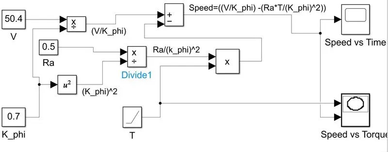
According to the given equation,we can conclude the following results:-
- The speed is non zero even if the torque is zero as the motor runns on no-load at that time.
- Due to the nature of the Torque chosen (linearly increasing), the speed curve is linearly decreasing.
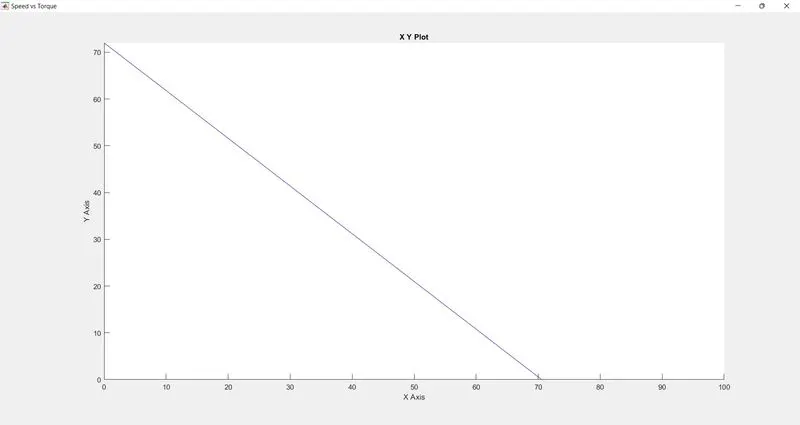
The above results have been justifed in the plots below:-
- Speed(rad/s) vs Torque(Nm) graph- (Y-axis=Speed;X-axis=Torque)
- Speed (rad/s) vs Time (s)
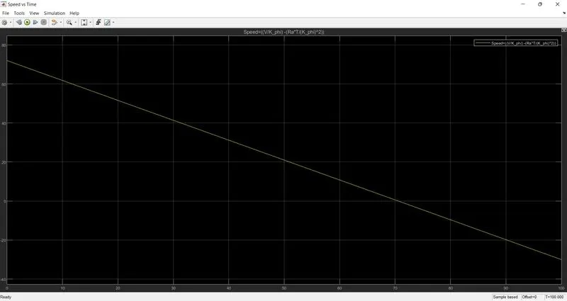
From the above plots we conclude:-
- No-load speed= 72 rad/s
- Stalling Torque= 72Nm
Solution 3:- The author writes this blog to entail the differences between the two most commonly used motor drives of the automobile industry-The DC brushless motor drive and the induction motor drive.Rippel goes into detail about the differences between the construction, working and the cost of the two drive types.However, with what he has written, he has not arrived on the conclusion that one type is better than the other.In the last lines of the opening paragraph, Rippel writes,"there is none engine type" and that all is a matter of personal prefernce when it comes to choosing an engine.it is in this same regard that he ends the blog stating that there is still 'no winner' when it comes to drive selection either.In spite of both motor drive types having similarities, they also have their benefits and drawbacks.
For DC brushless drives, we are told that their construction implements 2 or more permanent magnets at the rotor to generate a DC magnetic field.It also consists of a stator core(made up of thin,stacked laminations).It also uses an inverter for current control, meaning that it cannot run on DC supply as the current direction has to be changed repeatedly to maintain constant torque.
For induction drives, their rotor has no magnets but instead stack steel laminations with buried peripheral conductors which form a 'shorted structure'.It is the current in the stator windings that generates a rotating magnetic field which interacts with the rotor.
Induction motors can be used directy with power from the mains and do not require an inverter to start the drive and produce the starting Torque. It has the ability to start under the mains load applied.However, DC brushlessd drives cannot do the same.They cannot generate the starting Torque when connected to the mains supply.They reuire an inverter to do this.
Induction motor drives cannot run on DC power supply and are solely dependent on AC power supply.Also, when they are connected to 3-phase mains supply having power frequency, the motor operates at constant speed and also have limited starting Torque and peak Torque.In order to rectify this, an inverter can be used to operate the induction motor drive with DC or battery.Also, if the inverter frequency is varied, then the speed can be made available.
Difference between DC brushless motor and induction motor is given below:-
| S.No. | DC BRUSHLESS MOTOR | INDUCTION MOTOR |
| 1. | DC Supply | AC Supply |
| 2. | Require position sensor | Require speed sensor |
| 3. | The torque generated due to interaction between rotor and stator magnetic field. | Stator's rotating magnetic field interacts with the rotor laminations and induces rotor magnetic field, which interacts with stator magnetic field and produces torque. |
| 4. | The rotor includes two or more permanent magnets to generate magnetic field | The rotor includes stacked steel laminations with shorted peripheral conductors for induced magnetic field |
| 5. | Less rotor heat generated,easier rotor cooling, higher peak point efficiency.Power factor upto 100% can be achieved. | Rotor cooling is difficult.Power factor can be achieved uto a maximum value of 85%. |
| 6. | Permanent magnets are costly and ferromagnets can not be brought near the motor. | Difficult to control, complex control laws for inverters. |
| 7. | As for size increases, losses increase and part-load efficiency decreases. | As for size increases, losses remain approximately same. |
| 8. | The magnetic field strength can't be adjusted so a single torque output can be produced. | The magnetic field strength can be varied as a function of the voltage supply and frequency for optimized torque output. |
| 9. | Preferred for HEV | Preferred for pure EV with high performance. |