Week-6 Challenge: EV Drivetrain
Introduction to power electronic conveters used in electric vehicle:
Power electronic converters play the role of taking electrical energy from the power system and turning it into a suitable form needed by a motor. The power electronic converter may be determined according to the given power source and the driving motor.
We know that power electronic devices are a combination of converter and controller where the converter functions according to the control signal generated by the controller. A power electronic converter is composed of power semiconductor devices controlled by integrated circuits.
An important aspect of converters is signal conditioning. Signal conditioning offers signals of the pure form i.e., free from harmonics. In a general way, it is said that getting an absolutely clear signal is impossible. But we can reduce harmonics to some extent using a simple low pass LC filter.
Types of power conveters:
Static Power converters (switchs) execute power conversion quite efficiently. Power electronic switches have solid-state devices with components like inductors and capacitors. Generally, inductors and capacitors exhibit negligible power loss characteristics in comparison to resistors
- AC TO DC POWER CONVETERS (RECTIFIRES)
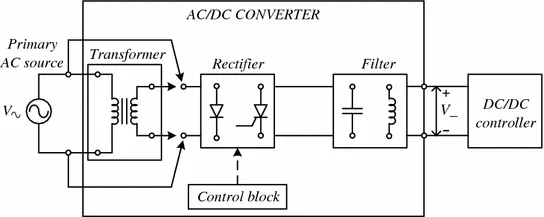
A type of converter that changes input AC signal into a DC is known as AC to DC converter. the devices that convert the AC signal into DC signal are known as rectifiers
AC TO DC can be further classified
- Diode Rectifiers: This rectifier circuit changes applied ac input voltage into a fixed dc voltage. Either a single-phase or three-phase ac signal is applied at the input. These are mainly used in electric traction and in electrochemical processes like electroplating along with in battery charging and power supply. These are also used in welding and UPS related services.
- Phase Controlled Rectifiers: Unlike diode rectifiers, phase-controlled rectifiers are designed to convert a fixed value of ac signal voltage into a variable dc voltage. Here line voltage operates the rectifier hence these are sometimes known as line commutated ac to dc converters. Similar to diode rectifiers, here also the applied ac signal can be a single-phase or three-phase ac signal. Its major applications are in dc drives, HVDC systems, compensators, metallurgical and chemical industries as well as in excitation systems for synchronous machines.
DC DC CONVETERS(CHOPPERS):
The different configurations of EV power supply show that at least one DC/DC converter is necessary to interface the FC, the Battery or the Supercapacitors module to the DC-link.
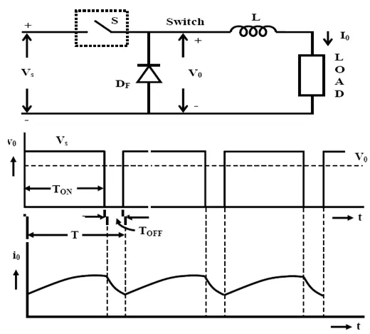
DC to DC converter is a category of power converters and it is an electric circuit which converts a source of direct current (DC) from one voltage level to another, by storing the input energy temporarily and then releasing that energy to the output at a different voltage. The storage may be in either magnetic field storage components (inductors, transformers) or electric field storage components (capacitors).
DC/DC converters can be designed to transfer power in only one direction, from the input to the output. However, almost all DC/DC converter topologies can be made bi-directional. A bi-directional converter can move power in either direction, which is useful in applications requiring regenerative braking.
The amount of power flow between the input and the output can be controlled by adjusting the duty cycle (ratio of on/off time of the switch). Usually, this is done to control the output voltage, the input current, the output current, or to maintain a constant power. Transformer-based converters may provide isolation between the input and the output. The main drawbacks of switching converters include complexity, electronic noise and high cost for some topologies. The most common DC/DC converters can be grouped as follows:
Non-isolated converters
The non-isolated converters type is generally used where the voltage needs to be stepped up or down by a relatively small ratio (less than 4:1). And when there is no problem with the output and input having no dielectric isolation. There are five main types of converter in this non-isolated group, usually called the buck, boost, buck-boost, Cuk and charge-pump converters. The buck converter is used for voltage step-down, while the boost converter is used for voltage step-up. The buck-boost and Cuk converters can be used for either step-down or step-up. The charge-pump converter is used for either voltage step-up or voltage inversion, but only in relatively low power applications.
Isolated converters
Usually, in this type of converters a high frequency transformer is used. In the applications where the output needs to be completely isolated from the input, an isolated converter is necessary. There are many types of converters in this group such as Half-Bridge, Full-Bridge, Fly-back, Forward and Push-Pull DC/DC converters. All of these converters can be used as bi-directional converters and the ratio of stepping down or stepping up the voltage is high.
DC to AC Converters(inverters)
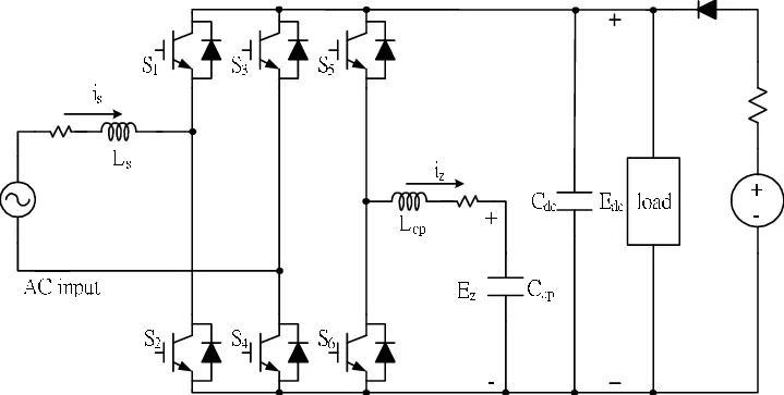
The devices that are designed to convert the dc signal into ac signal are known as inverters. The applied input is a fixed dc voltage that can be obtained from batteries but the output obtained is variable ac voltage. The voltage and frequency of the signal obtained are of variable nature. Here the semiconductor device i.e., the thyristor is turned off by using either line, load, or forced commutation.
Thus, it can be said that by the use of inverters, a fixed dc voltage is changed into an ac voltage of variable frequency. Generally, the semiconductor devices used for its fabrication are power transistors, MOSFETs, IGBT, GTO, thyristors, etc.
Inverters mainly find applications in induction motor and synchronous motor drives along with UPS, aircraft, and space power supplies. In high voltage dc transmission system, induction heating supplies as well as low power systems of mobile nature like flashlight discharge system in photography camera to very high power industrial system.
Like choppers, in inverters also conventional thyristors are used in high power applications and power transistors are used in low power applications.
AC to AC Converters
An ac to ac converter is designed to change the ac signal of fixed frequency into a variable ac output voltage.
There are two classifications of ac to ac converters which are as follows:
Cycloconverters: A cycloconverter is a device used for changing ac supply of fixed voltage and single frequency into an ac output voltage of variable voltage as well as different frequency. However, here the obtained variable ac signal frequency is lower than the frequency of the applied ac input signal. It adopts single-stage conversion. Generally, line commutation is mostly used in cycloconverters however forced or load commutated cycloconverters are also used in various applications.
These mainly find applications in slow-speed large AC traction drives such as a rotary kiln, multi MW ac motor drives, etc
AC Voltage Controllers (AC voltage regulators): The converters designed to change the applied ac signal of fixed voltage into a variable ac voltage signal of the same frequency as that of input. For the operation of these controllers, two thyristors in an antiparallel arrangement are used. Line commutation is used for turning off both the devices. It offers the controlling of the output voltage by changing the firing angle delay.
The major applications of ac voltage controllers are in lighting control, electronic tap changers, speed control of large fans and pumps as well
MODULE 2#
An Electric Vehicle's powertrain with 72V battery pack in shown in the diagram below. The duty ratio for acceleration operation is 'd1' and for the braking operation the duty ratio is 'd2
The other parameters of the electric vehicle is given below,
Motor and Controller Parameters:
Rated Armature voltage(Va)= 72 V
Rated armature current(Ia)= 400 A
Ra= 0.5Ω, KΦ= 0.7 Volt second
Chopper Switching frequency= 400 Hz
The vehicle speed-torque characteristics are given by the below equation
 ...............................(eqn 1)
What is EV steady state speed if duty cycle is 70?
solution
as we know that duty cycle is 70%
duty cycle ratio of on/off time of the switch.
Duty cycle, sometimes called "duty factor," is expressed as a percentage of ON time. A 70% duty cycle is a signal that is ON 70% of the time and OFF the other 30%
duty cycle=0.7
actual voltage can be calculated
V=0.7*Rated Armature voltage(Va)
therefore actual voltage =0.7*72
=50.4v
torque equation for motor
Tm=Vkϕ/R_a -((kϕ)^2/R_a )⋅ω
Tm=50.4*0.7/0.5-((0.7)^2/0.5)*ω........................eqn2
Tm=70.56-0.98*ω
comparing both the equation 1 and 2
at steady state motor torque and vehicle torque both are equal
there fore
at steady state
Tm=Tv
70.56-0.98*ω=24.7+(0.0051)*ω^2
0.0051ω^2+0.98ω+45.86=0
the solution of this eqn can by finding roots of quadratic equation
therefore
ω=38.915 rad/sec and the other root of ω=-231.072 rad /sec
hence if the duty cycle is 70% the steady state speed is 38.915 rad/sec =371.79 RPM
MODULE 3#
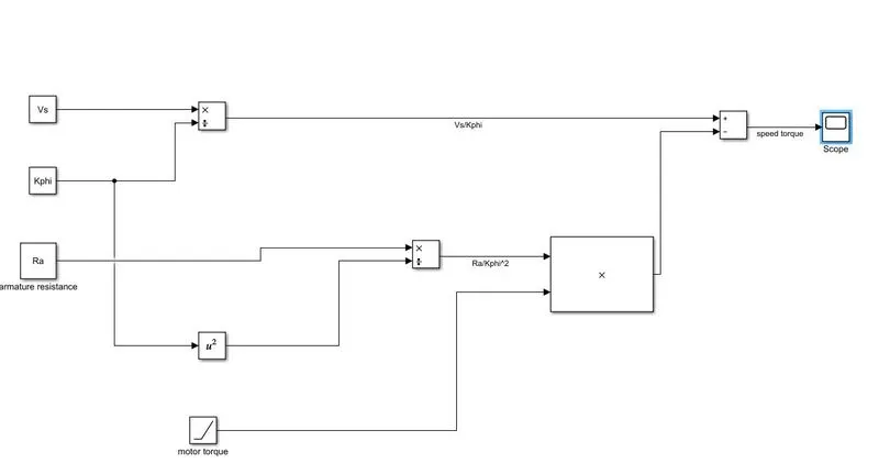
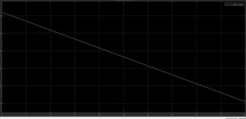
Develop a mathematical model of a DC Motor for the below equation using Simulink.
ω= V/Kϕ"-Ra/Kϕ^2.T
RESULTS#
MODULE 4#
Wally Rippel is a long-time proponent of electric vehicles. Prior to joining Tesla Motors, he was an engineer at AeroVironment, where he helped develop the EV1 for General Motors . Wally has also worked for the Jet Propulsion Laboratory on electric vehicle battery research, . In 1968, as a Caltech undergraduate student, he built an electric car (a converted 1958 Volkswagen microbus) and won the Great Transcontinental Electric Car Race against MIT.
ONE SIZE DOESNOT FIT FOR ALL:
wally rippel said in this world all the gas powered vehicle are not same.means they have differnt engine configuration and depends on that configuration one chose the best one depending upon is requirement like price and performance and same is true for electric vehicles.
he also told when he was young there were lead acid batteries, DC brush motors, and contactor controllers which was replaced in todays era lead acid battery was replaced by lithium ion battery ,dc brush motors was replaced by dc brushless motors or induction motors.Contactors, meanwhile, have given way to modulating inverters.
in A Closer Look
he said what are these two technologies? How do they work? What differentiates them? And what do they have in common? Let’s start with DC brushless drives
DC BRUSHLESS DRIVES :
With brushless machines, the rotor includes two or more permanent magnets that generate a DC magnetic field . In turn, this magnetic field enters the stator core (a core made up of thin, stacked laminations) and interacts with currents flowing within the windings to produce a torque interaction between the rotor and stator. As the rotor rotates, it is necessary that the magnitude and polarity of the stator currents be continuously varied – and in just the right way - such that the torque remains constant and the conversion of electrical to mechanical energy is optimally efficient. The device that provides this current control is called an inverter. Without it, brushless motors are useless motors.
INDUCTION MOTOR DRIVES:
the stators for the 3-phase induction motor and the DC brushless motor are virtually identical. Both have three sets of “distributed windings” that are inserted within the stator core. The essential difference between the two machines is with the rotor.
Unlike the DC brushless rotor, the induction rotor has no magnets – just stacked steel laminations with buried peripheral conductors that form a “shorted structure.” Currents flowing in the stator windings produce a rotating magnetic field that enters the rotor. In turn, the frequency of this magnetic field as “seen” by the rotor is equal to the difference between the applied electrical frequency and the rotational “frequency” of the rotor itself. Accordingly, an induced voltage exists across the shorted structure that is proportionate to this speed difference between the rotor and electrical frequency. In response to this voltage, currents are produced within the rotor conductors that are approximately proportionate to the voltage, hence the speed difference. Finally, these currents interact with the original magnetic field to produce forces – a component of which is the desired rotor torque.
When a 3-phase induction motor is connected to utility type 3-phase power, torque is produced at the outset; the motor has the ability to start under load. No inverter is needed. (Were an inverter needed, Tesla’s invention would have been useless until sometime in the 1960s.) The fact that induction motors are directly compatible with conventional utility power is the main reason for their success. In contrast, a brushless DC motor produces no starting torque when directly connected to fixed frequency utility power. They really need the aid of an inverter whose “phase” is maintained in step with the angular position of the rotor.
hile 3-phase induction motors have great utility, they also have some severe limitations. They cannot operate from DC; AC is a must. Shaft speed is proportionate to line frequency. Hence, when used with utility power, they are constant speed machines. Finally, when operated from utility power, they have limited starting torque and somewhat limited running peak torque capabilities, when compared to DC type machines.
Brushless or Induction?
Back in the 1990s all of the electric vehicles except one were powered by DC brushless drives. Today, all the hybrids are powered by DC brushless drives, with no exceptions. The only notable uses of induction drives have been the General Motors EV-1; the AC Propulsion vehicles, including the tzero; and the Tesla Roadster.
Both DC brushless and induction drives use motors having similar stators. Both drives use 3-phase modulating inverters. The only differences are the rotors and the inverter controls. And with digital controllers, the only control differences are with control code. DC brushless drives require an absolute position sensor, while induction drives require only a speed sensor; these differences are relatively small.
One of the main differences is that much less rotor heat is generated with the DC brushless drive. Rotor cooling is easier and peak point efficiency is generally higher for this drive. The DC brushless drive can also operate at unity power factor, whereas the best power factor for the induction drive is about 85 percent. This means that the peak point energy efficiency for a DC brushless drive will typically be a few percentage points higher than for an induction drive.
In contrast, induction machines have no magnets and B fields are “adjustable,” since B is proportionate to V/f (voltage to frequency). This means that at light loads the inverter can reduce voltage such that magnetic losses are reduced and efficiency is maximized. Thus, the induction machine when operated with a smart inverter has an advantage over a DC brushless machine – magnetic and conduction losses can be traded such that efficiency is optimized. This advantage becomes increasingly important as performance is increased. With DC brushless, as machine size grows, the magnetic losses increase proportionately and part load efficiency drops. With induction, as machine size grows, losses do not necessarily grow. Thus, induction drives may be the favored approach where high-performance is desired; peak efficiency will be a little less than with DC brushless, but average efficiency may actually be better.