Week-6 Challenge: EV Drivetrain
Aim: Which types of power converter circuits are employed in electric and hybrid electric vehicle?
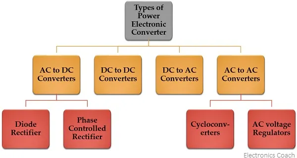
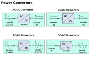
Theory: The most commonly used power converters used in EV and HEV are DC/DC converter and DC/AC converter.
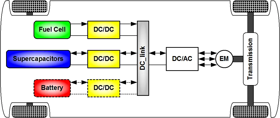
In reference (Schaltz & Rasmussen, 2008), 10 cases of combining the fuel cell with the battery, SCs, or both are investigated. The system volume, mass, efficiency, and battery lifetime were compared. It is concluded that when SCs are the only energy storage device the system becomes too big and heavy. A fuel cell/battery/supercapacitors hybrid provides the longest life time of the batteries. It can be noticed that the use of high power DC/DC converters is necessary for EV power supply system. The power of the DC/DC converter depends on the characteristics of the vehicle such as top speed, acceleration time from 0 to 100 Km/h, weight, maximum torque, and power profile (peak power, continuous power). Generally, for passenger cars, the power of the converter is more than 20 KW and it can go up to 100 KW.
The different configurations of EV power supply show that at least one DC/DC converter is necessary to interface the FC, the Battery or the Supercapacitors module to the DC-link.
In electric engineering, a DC to DC converter is a category of power converters and it is an electric circuit which converts a source of direct current (DC) from one voltage level to another, by storing the input energy temporarily and then releasing that energy to the output at a different voltage. The storage may be in either magnetic field storage components (inductors, transformers) or electric field storage components (capacitors).
DC/DC converters can be designed to transfer power in only one direction, from the input to the output. However, almost all DC/DC converter topologies can be made bi-directional. A bi-directional converter can move power in either direction, which is useful in applications requiring regenerative braking.
Classification of Power Converter:
Aim: An Electric Vehicle's powertrain with 72V battery pack in shown in the diagram below. The duty ratio for acceleration operation is 'd1' and for the braking operation the duty ratio is 'd2'.
Ans:
This is torque requirement of the vehicle which is directly given in the question
T = 24.7 + 0.0051*(w)^2-------------------------------------Eq(1)
Next, we know the torque speed characteristic of the motor. We are provided with armature current , voltage and duty cycle.
So the average voltage is given given as product of battery voltage and duty cycle
Vo = Battery voltage * duty cycle
Vo = 50.4
So the average voltage is 50.4 V.
The torque speed equation is given as shown below
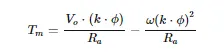
Tm = 50.4*0.7/0.5 - w*(0.7)^2/0.5
Tm = 70.56 - 0.98*w--------------------------------------Eq(2)
Now we have 2 torque equation that in term of angular speed, the first equation is for vehicle torque requirement and the second one is motor torque
equating both
24.7 + 0.0051*(w)^2 = 70.56 - 0.98*w
on solving this equation we get two solution one is positive and second is negative.
As we know angular speed cannot be negative
So ,
Angular speed(w) = 38.91 rad/sec
Aim: Develop a mathematical model of a DC Motor for the below equation using Simulink.
ω">ωω= V/Kϕ">ϕϕ -Ra/Kϕ">ϕϕ^2 .T
Model: we have model the avobe equation in simulink where we have given a ramp input as torque value
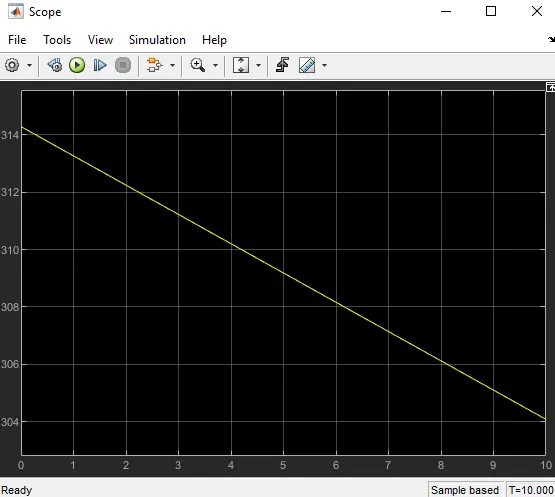
and we get corresponding speed values as output from scope block.
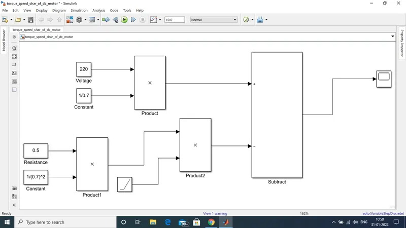
Here all the values of voltage, constants and the resistance are assumed.
Output: Output graph shows the plot between speed in y axis and torque in x axis.
Aim: Refer to the blog on below topic:
Induction Versus DC brushless motors by Wally Rippel, Tesla
Explain in brief about author’s perspective.
Answer: In this blog Wally Rippel shares his views on DC brushless and induction motor
Lets us first know who is Wally Rippel?
Wally Rippel is a long-time proponent of electric vehicle. He was engineer at AeroVironment where he has helped General Motors with EV1. Wally has also worked for the Jet propulsion Laboratory on electric vehicle battery research.
Further in his discussion he said "One Size Does Not Fit All". which is very true in our real life too. Just for an example when we go to market to purchase some cloths its not that whats suits me and fits me will be the same with my brother. As i gave an example of clothes he said about engines that In this world engines are of different types. And non of this engine is best one. The only purpose of these many engine are based on different requirement and Prices one can use any of the engine type.
Next he said that all the older technologies are replaced by efficient new technologies he also gave some example such as Lead has been replaced by lithium and DC by either DC brushless or induction.
He took close look on what are these two technologies? How do they work? What differentiates them? And what do they have in common?
Starting with brushless motor he said rotor has two or more permanent magnet that generate a DC magnetic field. In turn, this magnetic field enters the stator core (a core made up of thin, stacked laminations) and interacts with currents flowing within the windings to produce a torque interaction between the rotor and stator. As the rotor rotates, it is necessary that the magnitude and polarity of the stator currents be continuously varied – and in just the right way - such that the torque remains constant and the conversion of electrical to mechanical energy is optimally efficient. The device that provides this current control is called an inverter. Without it, brushless motors are useless motors.
Next he spoke about induction motor drives. He said 3 phase induction motor was invented by Nikola Tesla.The stators for the 3-phase induction motor and the DC brushless motor are virtually identical. Both have three sets of “distributed windings” that are inserted within the stator core. The essential difference between the two machines is with the rotor.
Then he said Unlike the DC brushless rotor, the induction rotor has no magnets. It ha just stacked steel laminations with buried peripheral conductors that form a “shorted structure.” Currents flowing in the stator windings produce a rotating magnetic field that enters the rotor. In turn, the frequency of this magnetic field as “seen” by the rotor is equal to the difference between the applied electrical frequency and the rotational “frequency” of the rotor itself. Accordingly, an induced voltage exists across the shorted structure that is proportionate to this speed difference between the rotor and electrical frequency. In response to this voltage, currents are produced within the rotor conductors that are approximately proportionate to the voltage, hence the speed difference. Finally, these currents interact with the original magnetic field to produce forces – a component of which is the desired rotor torque.
When a 3-phase induction motor is connected to utility type 3-phase power, torque is produced at the outset; the motor has the ability to start under load. No inverter is needed.
Next he talks about what do you preffer brushless or induction?
After the discussion he concluded that 'No one is Winner' according to the requirement , purpose we can use and of these motors.
Below is an image showing difference between Brushless DC motor and AC induction motor.