Week-6 Challenge: EV Drivetrain
1. Which types of power converter circuits are employed in an electric and hybrid electric vehicle?
The power converter topologies depend on the motors to be driven. The selection criteria of motor drives, including the motors and their power converters, for EVs, can be divided into the mandatory requirements and the preferable requirements. The mandatory ones are that the motor drive can offer the torque-speed requirements of the EV driving profile without involving variable gearing or gearbox, and the motor drive can provide the capability of bidirectional power flow to recover the regenerative braking energy. In general, the DC, AC, or SR motor drives can offer the desired torque-speed requirements under proper motor design. The preferable requirements of EV motor drives are low cost, high efficiency, high power density, high controllability, and maintenance-free operation.
For electric vehicular systems, there is a need for a highly reliable, flexible, and fault-tolerant electrical power processing system onboard to deliver high quality of power based on vehicle demands. At present, this responsibility has been taken care of by the available PEC that includes DC/DC converters, rectifiers (DC/AC), inverters (AC/DC), and battery chargers composed of AC/DC and or DC/DC converters. Individually or combination of these converters can be taken to serve the purpose; however, the operation of each PEC is entirely different from the other. PECs perform some of the critical tasks like ON/OFF switching of various loads; power conditioning and voltage/current modulation to create compatibility among the energy source system (ESS), traction motors, and auxiliary loads.
In the advanced architecture of a vehicle's electrical power system, it is expected to have a single DC voltage bus with different voltage level distribution and intelligent power and load management. The modern Architecture of electric power systems for vehicular application is shown in Fig. In this architecture, different energy sources and vehicle loads having distinct V-I characteristics and dynamic responses are interfaced with common DC buses through PECs. Since PECs are controlling, manage, and optimizing the power flow among energy sources and vehicle loads, therefore it is considered as the heart of the electric propulsion system.
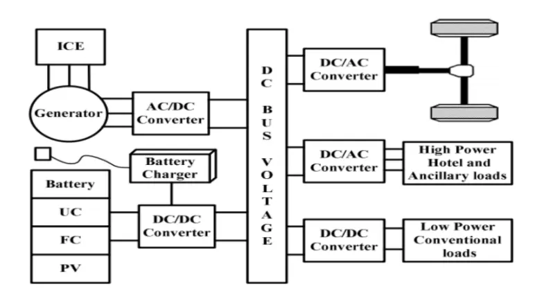
DC/DC Converters:
A DC/DC converter in its basic form converts unregulated DC input voltage at a certain level to a regulated DC output voltage at a different level with very high conversion efficiency (>90%). Modern-day DC/DC converters are operated at high
frequencies (10 kHz - 1 MHz). The size of the components such as inductors, transformers, and capacitors is reduced at high-frequency operation. Transistors such as MOSFETs and IGBTs are used as switches. The former is preferred in high frequency, low, and medium power applications, whereas the latter is preferred in low-frequency high power applications. The switches are turned ON and OFF by pulse- width modulation (PWM) technique. In addition, the role of DC/DC converter is very significant especially in terms of better utilization of energy sources, power management, dynamic performance, flexibility, system optimization, and reduction of weight and cost.
From the architecture of the HES, the DC/ DC converters used in EVs may be used for:
1. Providing low voltage (12V or 14V) for low voltage loads.
2. Boost the voltage level of the battery such that it matches the level of the DC bus voltage for driving the AC motor inverter if the traction motor is an AC motor.
3. Motor propulsion if the traction motor is a DC motor.
DC/AC Converters:
A suitable DC/AC inverter draws DC power from the batteries to drive the electric traction motor, which in turn provides power to the wheels. The DC/AC inverter also performs the function of recharging the batteries during regenerative braking in HEVs. Also, Inverters are used for supplying utility loads such as Air conditioning and power outlets. Inverters are generally classified into voltage-fed and current-fed types. Because of the need for a large series inductance to emulate a current source, current-fed inverters are seldom used for EV propulsion. In fact, voltage-fed inverters are almost exclusively used because they are very simple and can have power flow in either direction. A typical three-phase full-bridge voltage-fed inverter.
The output waveform of an inverter may be rectangular, six-step, or pulse width modulation (PWM), depending on the switching strategy for different applications. For example, a rectangular output waveform is produced for a PM brushless DC
motor, while a six-step or PWM output waveform is for an induction motor. It should be noted that the six-step output is becoming obsolete because its amplitude cannot be directly controlled and rich in harmonics. On the other hand, the PWM waveform is harmonically optimal and its fundamental magnitude and frequency can be smoothly varied for speed control. Starting from the last decade, numerous PWM switching schemes have been developed for voltage-fed inverters, focusing on the harmonic suppression, better utilization of DC voltage, tolerance of DC voltage fluctuation as well as suitability for real-time and microcontroller-based implementation.
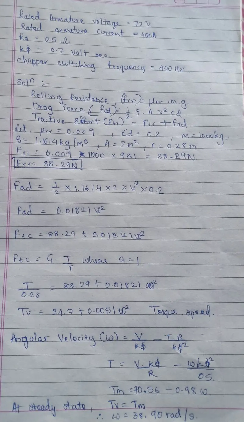
2. An Electric Vehicle's powertrain with a 72V battery pack is shown in the diagram below. The duty ratio for acceleration operation is 'd1' and for the braking operation the duty ratio is 'd2'.
clear all
close all
clc
I=400;
R=0.5;
k=0.7;
f=400;
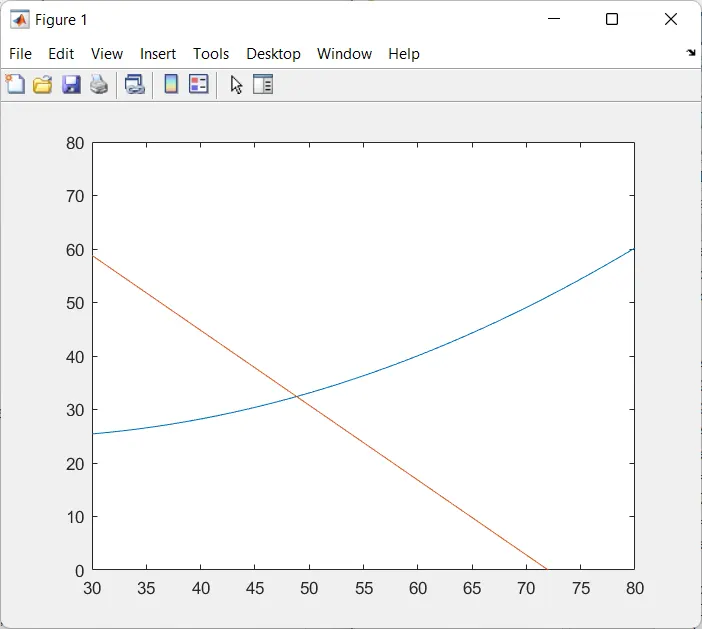
omega=linspace(0,100,50); % Speed torque characterstics equation
Tv=24.7+0.0051*omega.^2;
V=72*0.7;
Tm=70.56-0.98*omega;
omega=(V/k)-((R*Tm)/k);
plot(omega,Tv)
hold on
plot(omega,Tm)
axis([30 80 0 80])
xlable('Speed(rad/s)')
ylabl('Torque(N-m)')
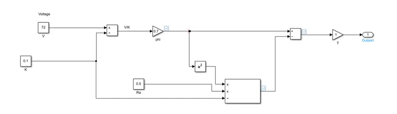
3. Develop a mathematical model of a DC Motor for the below equation using Simulink.
ω= V/Kϕ -Ra/Kϕ^2 .T
4. Induction motors vs Dc brushless by Walley Rippel, Tesla.
The author Wally Rippel has expressed the working principle of induction and DC brushless motors. The induction motor is old technology but it has an immense significant advantage over the DC brushless motor in pure electric vehicles. And author explains the significance of hybrid and plug-ins achieved and their dominant uses in the current market.
The heat generated from the rotor is less hence rotor cooling is easy and peak point efficiency is higher than the DC brushless. Inverter whose face is maintained in a step with the angular position of the router is mandatory without which DC brushless motor is useless. The magnetic field strength cannot be easily adjusted because of the permanent magnets. In DC brushless motor as its size increases the magnetic loss also increases. Permanent magnets are extensive.
no need for an inverter the motor has the ability to start under load. since they do not have any magnets controlling the magnetic field here it has magnetic losses ready hysteresis current resistance losses are minimized and the efficiencies maximized. induction drivers may be the favored approach where high performance is decided peak efficiency will be a little less than the DC brushless but an average deficiency may actually be better. Induction motors are less expensive when compared to the DC brushless. They cannot operate from a DC, AC source is a must. When operated from a utility power they have limited starting torque and somewhat limited running feet or capability is when compared to dc type machines. even by adding the inverter, the torque performance is slow when compared to the DC motor.