Week-6 Challenge: EV Drivetrain
Q. (1) - Which types of power converter circuits are employed in electric and hybrid electric vehicle?
A. - A power converter is an electrical circuit that changes the electric energy from one form into the desired form optimized for the specific load. A converter may do one or more functions and give an output that differs from the input. It is used to increase or decrease the magnitude of the input voltage, invert polarity, or produce several output voltages of either the same polarity with the input, different polarity, or mixed polarities such as in the computer power supply unit.
The converter acts as the link or the transforming stage between the power source and the power supply output.
In simple terms, the task of a power converter is to process and control the flow of electric energy by supplying voltages and currents in a form that is optimally suited for the user loads.
There are several kinds of converters based on the source input voltage and the output voltage and these fall into four categories -
- AC-DC converter known as the Rectifier.
- DC-DC converter known as the Chopper.
- DC-AC converter known as the Inverter.
- AC-AC converter known as Cycloconverter or Frequency Changer.
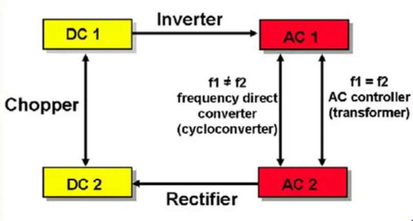
Note : Typically, the Electric and Hybrid Electric vehicles have no use of the AC-AC converters in their construction.
AC-DC converter or Rectifier :
- Electric power is transported on wires either as a direct current (DC) flowing in one direction at a non-oscillating constant voltage, or as an alternating current (AC) flowing backwards and forwards due to an oscillating voltage. AC is the dominant method of transporting power because it offers several advantages over DC, including lower distribution costs and simple way of converting between voltage levels thanks to the invention of the transformer. AC power that is sent at high voltage over long distances and then converted down to a lower voltage is a more efficient and safer source of power in homes.
- The simplest AC/DC converters comprise of a transformer following the input filtering, which then passes onto a rectifier to produce DC. In this case, rectification occurs after the transformer because transformers do not pass DC.
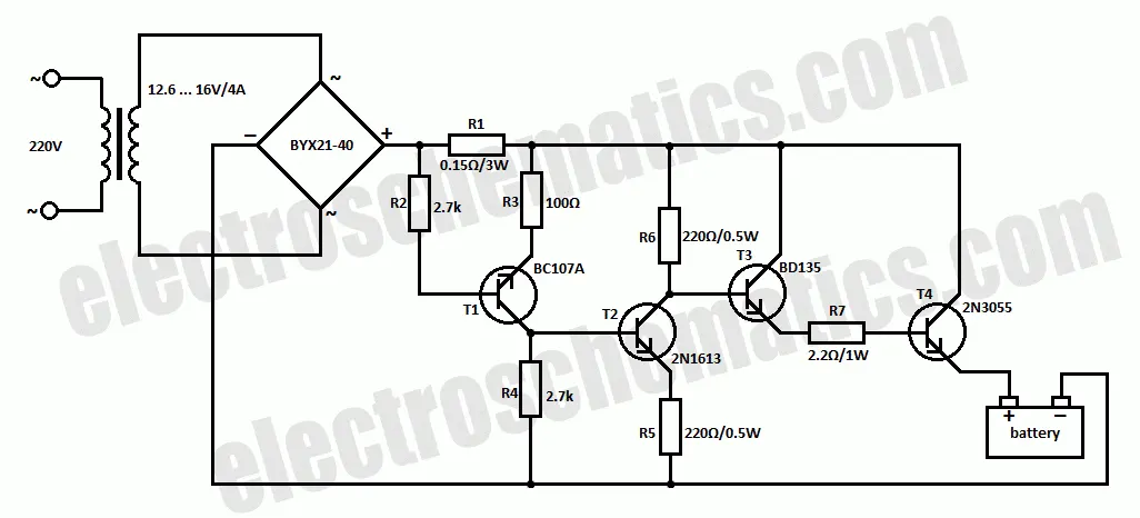
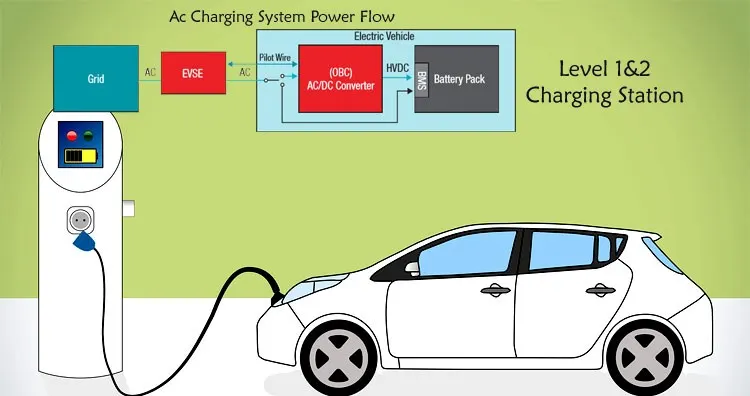
- In case of EVs or HEVs, such Rectifier is used inside the 'Onboard Charger' to charge the Car Battery. The AC power from the charging station is converted in DC power and the DC Battery can be charged.
DC-DC converter or Chopper :
- A DC to DC converter is an electronic circuit or electromechanical device that converts a source of direct current (DC) from one voltage level to another.
- DC to DC converters are used in portable electronic devices such as cellular phones and laptop computers, which are supplied with power from batteries primarily. Such electronic devices often contain several sub-circuits, each with its own voltage level requirement different from that supplied by the battery or an external supply (sometimes higher or lower than the supply voltage).
- These can be simply categorised in two classes -
Step-Up - To increase the voltage level.
Step-Down - To decrease the voltage level.
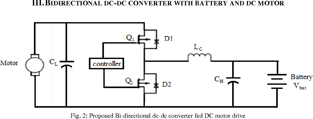
- In EVs and HEVs, these converters are used to power all the auxiliary devices that run on the car battery. Since, the auxiliary devices cannot run on the rated battery voltage, step-down choppers are placed to reduce the voltage levels according to the requirement.
- Also, if the Electric motor of the car is a DC Brushed motor type, a Chopper is employed there too.
DC-AC converter or Inverter :
- Power Inverters convert direct current (DC), the power that comes from a battery, into alternating current (AC), the kind of power supplied to our home and the power larger electronics need to function.
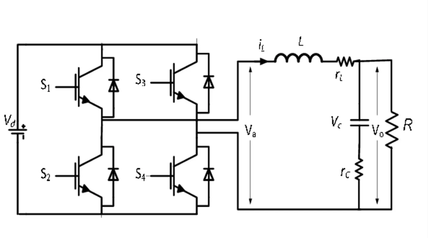
- In most of the EV and HEV applications, DC Brushless Induction motors are used.
- The Torque-Speed characterisitics of these motors closely resemble the DC brushed motors. However, the internal working of these type of motors is on AC power.
- So, the DC power from the car Battery needs to be converted into AC for the functioning of these Induction motors. Inverter is the device that performs this task.
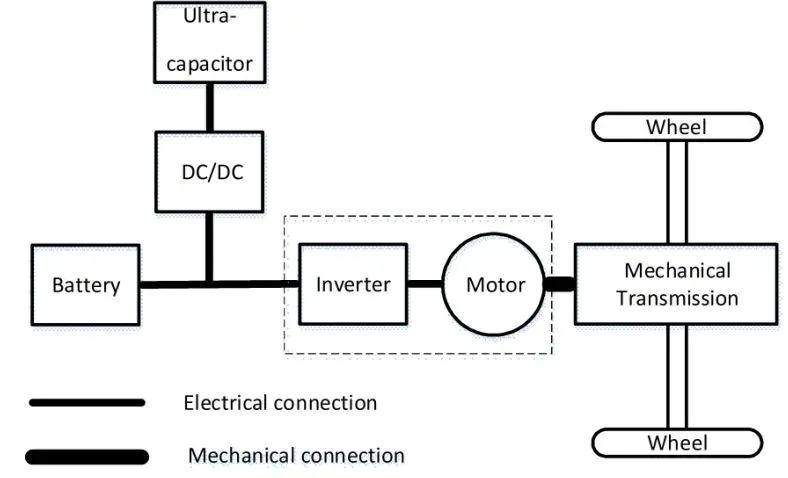
Q. (2) - An Electric Vehicle's powertrain with 72V battery pack in shown in the diagram below. The duty ratio for acceleration operation is 'd1' and for the braking operation the duty ratio is 'd2'.
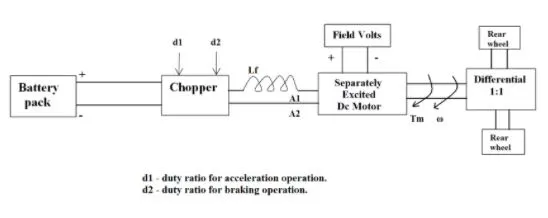
Motor and Controller Parameters :
Rated Armature voltage= 72 V
Rated armature current= 400 A
Ra= 0.5Ω, KΦ= 0.7 Volt second
Chopper Switching frequency= 400 Hz
The vehicle speed-torque characteristics are given by the below equation -

What is EV steady state speed if duty cycle is 70%?
Solution :
`T = 24.7 + (0.0051)omega^2` .... (given vehicle Speed-Torque relation)
The fundamental equation for the motor Speed-Torque characteristics is given as -
`T = (kphi)^2/(Ra)((d.V)/(kphi)-omega)`
Where,
T - Motor torque (N-m)
`kphi`- Motor constant (Volt-s or Weber)
Ra - Armature resistance (ohms)
d - duty cycle
V - rated armature voltage (Volts)
`omega` - motor speed (rad/s)
Substituting all the given values in this equation, we get -
`T = (72 - omega)*(0.98)`
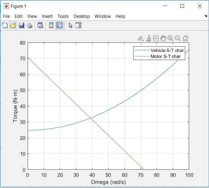
The steady state speed of the EV is the speed at which the vehicle Speed-Torque characteristics matches the Electric Motor's Speed-Torque characteristics.
∴ `24.7 + (0.0051)omega^2 = (72 - omega)(0.98)`
∴ `0.0051omega^2 + 0.98omega - 45.86 = 0`
Solving the above quadratic equation, we get,
`omega` = 38.91 rad/s OR `omega` = -231.07 rad/s
Assuming the vehicle is accelerating and not braking, the positive value is the required steady state speed.
∴ `omega` = 38.91 rad/s = 371.5 rpm
This can be visualised with the help of MATLAB too -
clear all;
close all;
clc;

% Input Parameters
V = 72;                                        % rated Armature Voltage (volts)
Ra = 0.5;                                      % Armature resistance (ohms)
kphi = 0.7;                                    % Motor constant (Volt-s or Weber)
d = 0.7;                                       % Duty Cycle

w = linspace(0,100,1000);

T1 = 24.7 + 0.0051.*(w.^2);                    % Given Vehicle S-T characteristics

T2 = ((kphi^2)/Ra).*((d*V)/(kphi)-w);          % Motor S-T characteristics

figure(1)
plot(w,T1);
hold on;
plot(w,T2)
legend('Vehicle S-T char','Motor S-T char');
axis([0 100 0 80]);
grid on;
xlabel('Omega (rad/s)');
ylabel('Torque (N-m)');
Output :
Q. (3) - Read the blog mentioned below and explain in brief about author’s perspective.
https://www.tesla.com/blog/induction-versus-dc-brushless-motors
- The author of the blog, Wally Rippel, is an experienced Power Electronics engineer. Being one of the valuable contributors in the development of the EV1 for General motors, he has a sound knowledge of the components involved in Electric vehicles.
He vaguely remembers that Lead batteries were primarily used back then in Electric vehicles. Over the course of years, these Lead batteries have been replaced by Lithium Ion batteries. Same goes with the electric motors. The conventional DC brushed motors got replaced by DC Brushless or Induction motors. - Judging by this phenomenon of constantly evolving and changing technological world, the Author tries to present his views regarding, whether or not the DC Brushless and Induction motors will stabilise in the Automotive industry or these, too, shall become obsolete very soon.
To answer this interesting, yet very much relevant question, author first explains the working and construction of each of the motors concerned. - A brushless DC machine includes 2 or more permanent magnets that generate the magnetic field. This magnetic field enters the stator core and and interacts with currents flowing within the windings to produce a torque interaction between the rotor and stator. As the rotor rotates, it is necessary that the magnitude and polarity of the stator currents be continuously varied such that the torque remains constant and the conversion of electrical to mechanical energy is optimally efficient. The device that provides this current control is called an Inverter.
- The Author points that these two motors are very much alike as far as the stator is concerned. The difference lies in their rotors.
Unlike the DC brushless rotor, the induction rotor has no magnets – just stacked steel laminations with buried peripheral conductors. Currents flowing in the stator windings produce a rotating magnetic field that enters the rotor. Accordingly, an induced voltage exists across the shorted structure that is proportionate to this speed difference between the rotor and electrical frequency. In response to this voltage, currents are produced within the rotor conductors that are approximately proportionate to the voltage, hence the speed difference. Finally, these currents interact with the original magnetic field to produce forces/torques. Here, no Invertor is needed. - The Author doesn't want to be biased by only pointing out the utility advantage of the Induction motor over the brushless DC motor. He also states the limitations of it -
These cannot operate on DC power, AC is a must. - He doesn't fail to point out that the rotors of the brushless DC motor produce much less heat, if compared with that of the Induction motor.
This is succeeded with him concluding that the peak power energy efficiency of DC brushless motors is slightly, yet notably, higher than the Induction motors. Also, these Induction motors are very complex and are difficult to establish control over the torque-speed range.
However, the permanent magnets involved in brushless motor case leads to considerable Eddy and Hysterisis losses. Even, such permanent magnets are very costly. This gives a cost advantage to the Induction motors over the former. - After this very thorough and detailed comparison, the Author comes back to his very first question. Is there any stability regarding the use of these two types of motors in the Automotive industry ?
As a conclusion, he says the DC brushless motors will likely dominate the Hybrid market while parallely, the Induction motors dominating the pure EV market.