Week-6 Challenge: EV Drivetrain
1. Which types of power converter circuits are employed in electric and hybrid electric vehicle?
AC to DC power converter-
AC-DC converters take the AC power from wall outlets and convert it to unregulated DC. These power supplies include transformers that change the voltage of the AC that comes through wall outlets, rectifies to save it from AC to DC and a filter that removes noise from the peaks and troths of the AC power waves. Typically, the voltage will be stepped down by the transformer to the voltage required by the device being supplied.
In the first step of converting AC to DC, the voltage is rectified using a series of diodes. This transforms the sinusoidal AC wave into a series of positive peaks using a rectifier. At this point, however, there is still waveform fluctuation - the time between the peaks - that needs to be removed.
To filter this out, a capacitor is used by creating a reservoir of energy that is then applied to the load when its voltage drops. The capacitor stores incoming energy on the rising edge and expands it when the voltage falls, significantly reducing instances of voltage droop. Generally, the higher the storage capacity of the capacitor, the higher the quality of the power supply.
After voltage conversion, output variation is smoothed out by passing the voltage through a regulator to create a fixed DC output.
Unregulated vs. regulated power supply
There are two varieties of AC power supply - unregulated and regulated.
In an unregulated supply, the ripple voltage stays in the output voltage. And because unregulated supplies exhibit ripple voltage, a regulated supply should always be used over an unregulated supply if there is any ambiguity regarding which should be used for a given device or application. This is because the ripple voltage can cause damage to electronic components. Many AC-DC power supplies include a regulator for this reason.
Dc to DC power converters-
Some devices - especially those powered by batteries or solar cells - require DC power at varying voltage levels, and this is where a DC-DC converter comes in. A DC-DC power supply converts direct current coming from the power source (a battery) from one voltage level to another depending on the point-in-time needs of the device being supplied.
In a portable electronic device, for example, a cellular phone, there are often several sub-circuits, each with its own voltage level requirement that differs from that supplied by the power supply. In addition, battery voltage decreases as stored energy is delayed.
How a DC-DC power supply works depends on the one in question; there are many different types of DC-DC converter (electronic, magnetic, non-isolated, buck-boost, etc.) and the type most appropriate for an application will depend on the device itself - from automobiles to portable devices.
However, many will include inverters and rectifiers that first convert DC power into AC power, which is then sent through a transformer to change the voltage. After attaining the correct voltage, the current travels back to the rectifier, where it is converted into DC power again.
Just like with AC power supplies, DC-DC power supplies may use regulators to smooth out the signal and eliminate ripple voltage.
DC to AC power conerters-
Also known as power inverters, DC to AC inverters are designed to change a DC (direct current) power supply to an AC (alternating current) power supply. DC is a relatively stable and positive voltage source and AC oscillates around a 0V base level, usually in a square or sinusoidal fashion.
The most common use for the inverter technologies is to change a battery source voltage into an AC signal, which can be used for almost all electronics today. Commonly, they are designed to operate with a 12V source since that is common in the automotive world, and lead-acid technology generally. An alternate use is an inverter system for photovoltaic cells. These solar panels often produce hundreds of volts in intense daylight and need special inverter systems to be able to align with household voltage requirements. The simplest circuitry required for an inverter is a transformer coil system and a switch.
A standard transformer is connected to the input DC signal via a switch, which quickly oscillates back and forth according the frequency requirements of the output. Because of the bi-directional current flow in the transformer’s primary coil, an AC signal is output through the secondary coils.
Buck-
A buck converter (step-down converter) is a DC to DC power converter which steps down voltage from its input (supply) to its output (load). It is a class of switched mode power supply (SMPS) typically containing at least two semiconductors a diode and a transistor, although modern buck converters frequently replace the diode with a second transistor used for synchronous rectification and at least one energy storage element, a capacitor,inductor, or the two in combination. To reduce voltage ripple, filters made of capacitors (sometimes in combination with inductors) are normally added to such a converter's output
(load-side filter) and input (supply-side filter).
Boost-
A boost converter (step-up converter) is a DC to DC converter that steps up voltage from its input (supply) to its output (load). It is a class of switched mode power supply (SMPS) containing at least two semiconductors a diode and a transistor and at least one energy storage element: a capacitor,inductor or the two in combination. To reduce voltage ripple, filters made of capacitors (sometimes in combination with inductors) are normally added to such a converter's output (load-side filter) and input (supply-side filter).
Buck-boost- The buck–boost converter is a type of DC to DC converter that has an output voltage magnitude that is either greater than or less than the input voltage magnitude. It is equivalent to a flyback converter using a single inductor instead of a transformer.
Cuk-
The Ćuk converter is a type of buck-boost converter with zero ripple current. Ćuk converter can be seen as a combination of boost converter and buckconverter, having one switching device and a mutual capacitor, to couple the energy.
charge-pump-
A charge pump is a kind of DC to DC converter that uses capacitors for energetic charge storage to raise or lower voltage. Charge-pump circuits are capable of high efficiences, sometimes as high as 90–95%, while being electrically simple circuits.
Half bridge-
A half-bridge converter is a type of DC-DC converter that, like flyback and forward converters, can supply an output voltage either higher or lower than the input voltage and provide electrical isolation via a transformer.
Full bridge-
The full-bridge converter adds two additional transistors to the half-bridge converter. This means that four transistors are available to provide power to the output section, so this type of converter is used in power supplies in excess of 1000 Watts. Each transistor has a clamping diode connected across its collector-emitter terminals and they are driven alternately in pairs. Transistors T1 and T3 are energized together for one half-cycle, and transistors T2 and T4 are energized together for the other half-cycle. One advantage of the full-bridge converter is that it only requires one capacitor for smoothing the output voltage, whereas the half-bridge converter required two. The full-bridge converter will be used in larger power supplies usually over 1000 Watts. Since this type of converter is more complex, it's normally used in the largest types of power supplies.
Push pull-
As the switch-mode power supply has evolved, additional adjustments to the original circuits have been made to get more power from smaller components. This means that the efficiency for the system must be increased. One simple way to do this is to use a center-tapped transformer that utilizes both the top and bottom half-cycles. The primary winding is controlled by two transistors, which allow one of them to conduct during each half-cycle, so the output is receiving voltage directly through one of them at all times. This means that the efficiency of this configuration is approximately 90%. This allows the overall size for the power supply to be smaller for a comparable power supply whose efficiency is 75% to 80%.
2. An Electric Vehicle's powertrain with 72V battery pack in shown in the diagram below. The duty ratio for acceleration operation is 'd1' and for the braking operation the duty ratio is 'd2'.
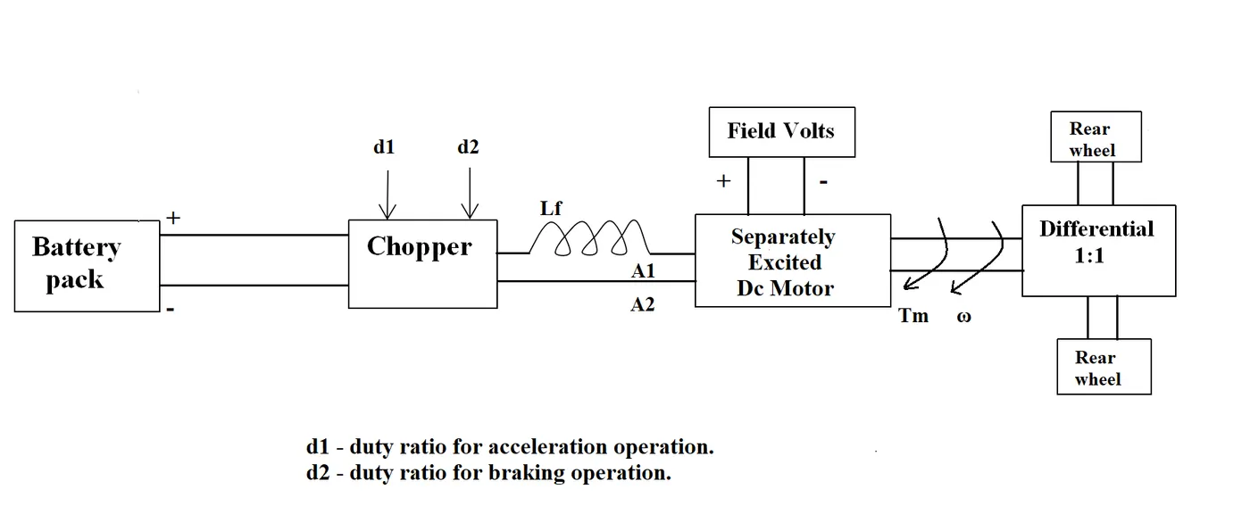
The other parameters of the electric vehicle is given below,
Motor and Controller Parameters:
Rated Armature voltage= 72 V
Rated armature current= 400 A
Ra= 0.5Ω, KΦ= 0.7 Volt second
Chopper Switching frequency= 400 Hz
The vehicle speed-torque characteristics are given by the below equation

What is EV steady state speed if duty cycle is 70%?
Given-
Battery Pack voltage(V) = 72 V
Rated armature current = 400 A
Armature Resistance(Ra) = 0.5
Motor Constant (K) = 0.7
Chopper Switching frequency = 400 Hz
Duty Cycle = 70%
Solution-
Vehicle Output Voltage() = Battery Voltage(V)*Duty Cycle
= 72*0.70
= 50.4 V
According to equation -
24.7 + 0.0051*w^2 = ((v*k)/R) - ((k^2)*w/R)
24.7 + 0.0051*w^2 = (72*0.7*0.7)/0.5 - (0.7^2/0.5)*w = 24.7 + 0.0051*w^2
70.56 - 0.98*w = 24.7 + 0.0051*W^2
w^2 + 192.15*w - 8992.15 = 0
Subsistute in below formulae
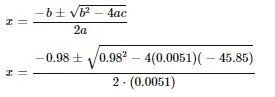
By applying in it we get,
w = 38.95 rad/sec
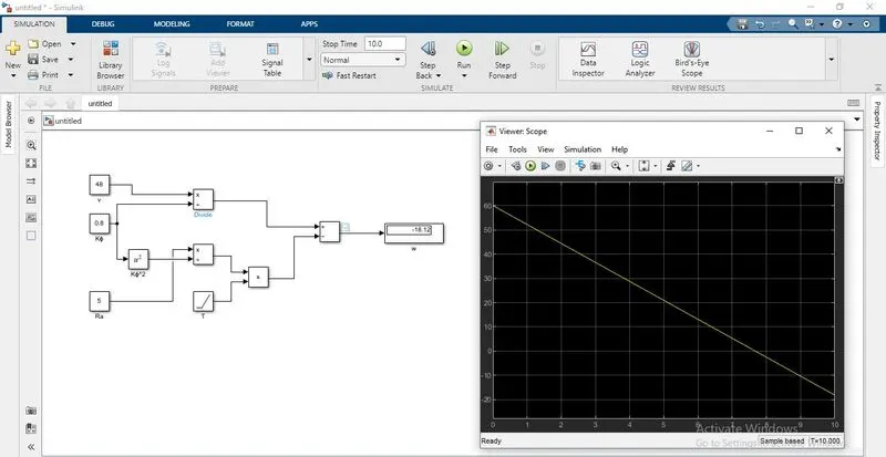
3. Develop a mathematical model of a DC Motor for the below equation using Simulink.
ω= V/Kϕ -Ra/Kϕ^2 .T
We have developed an simulation as shown and taken the output.
4. Refer to the blog on below topic:
Induction Versus DC brushless motors by Wally Rippel, Tesla
Explain in brief about author’s perspective.
Dc brushless motor-
A motor converts supplied electrical energy into mechanical energy. Various types of motors are in common use. Among these, brushless DC motors (BLDC) feature high efficiency and excellent controllability, and are widely used in many applications. The BLDC motor has power-saving advantages relative to other motor types.
Brushed DC motors, featuring simple design and easy control, are widely used to open and close disk trays. In cars, they are often used for retracting, extending, and positioning electrically-powered side windows. The low cost of these motors makes them suitable for many uses. One drawback, however, is that brushes and commutators tend to wear relatively quickly as a result of their continued contact, requiring frequent replacement and periodic maintenance.
Advantages-
The advantage of DC Brushless Motor is that there is low heat generation in the rotor and its cooling capacity is better as compared to Induction Motor. Also, peak point efficiency is generally higher for this drive. The DC brushless drive can also operate at unity power factor, whereas the best power factor for the induction drive is about 85%. This means that the peak point energy efficiency for a DC brushless drive will typically be a few percentage points higher than for an induction drive.
Disadvantage-
Rare-earth permanent magnets are much more expensive than other permanent magnets, which leads to an increase in motor costs. A large constant power range is critical to achieving high vehicle efficiency. It is impossible for a permanent magnet brushless DC motor to achieve a maximum speed greater than twice the base speed. During the manufacturing process of the motor, it may be dangerous because the large rare earth permanent magnets can attract scattered metal objects. In the event of a vehicle crash, if the wheels spin freely and the motor is still excited by permanent magnets, high voltages will appear at the motor terminals, which may endanger passengers or rescuers. The permanent magnet can be demagnetized by large reverse magnetomotive force and high temperature. The critical demagnetization force is different for each permanent magnet material. Care must be taken when cooling the motor, especially if the motor is compact. Surface-mounted motors of permanent magnets cannot achieve high speeds because this is limited by the mechanical strength of the assembly between the rotor yoke and the permanent magnets.
Induction Motor-
The technology behind the induction motor is that it basically uses a 3-phase induction motor which was invented by Nikola Tesla sometime before 1889. Unlike the DC brushless rotor, the induction rotor has no magnets – just stacked steel laminations with buried peripheral conductors that form a “shorted
structure.” Currents flowing in the stator windings produce a rotating magnetic field that enters the rotor. In an Induction motor current interacts with the Magnetic field generated by the stator to produce a force which is required for rotor torque. When a 3-phase induction motor is connected to utility type 3-phase power, torque is produced at the outset. The fact that induction motors are directly compatible with conventional utility power is the main reason for their useage.
Advantages
- The construction of the Stator is similar in both synchronous mototr well as induction motor. However, a slip ring is required to feed DC Supply to the Rotor in the case of a Synchronous Generator. These Slip rings are not required in a squirrel cage induction motor because the windings are permanently short circuited. When compared with a dc motor, the induction motor does not have Brushes and hence, maintenance required is quite low. This leads to a simple construction.
- The working of the motor is independent of the environmental condition. This is because the induction motor is Robust and mechanically strong.
- A Squirrel cage induction motor does not contain Brushes, Slip rings and Commutators. Due to this reason, the cost of the motor is quite low. However, Slip Rings are used in Wound type induction motor to add external resistance to the rotor winding.
- Due to the absence of Brushes, there are no sparks in the motor. It can also be operated in hazardous conditions.
- Unlike synchronous motors, a 3 phase induction motor has a high starting torque, good speed regulation and reasonable overload capacity.
- An induction motor is a highly efficient machine with full load efficiency varying from 85 to 97 percent.
Disadvantages
- A single phase induction motor, unlike a 3 phase induction motor, does not have a self starting torque. Auxiliaries are required to start a single phase motor.
- During light load conditions, the power factor of the motor drops to a very low value. This is because during the start, the motor draws a large magnetising current to overcome the reluctance offered by the air gap between the Stator and the Rotor. Also, the induction motor will take very less current from the supply main. The vector sum of Load current and Magnetising current lags the voltage by around 75-80 degrees and hence, the power factor is low. Due to high magnetising current, the copper losses of the motor increase. This in turn leads to decrease in the efficiency of the motor.
- speed control of an induction motor is very difficult to attain. This is because a 3 phase induction motor is a constant speed motor and for the entire loading range, the change in speed of the motor is very low.
- Induction motors have high input surge currents, which are referred to as magnetising inrush currents. This causes a reduction in voltage at the time of starting the motor.
- Due to poor starting torque, the motor cannot be used for applications which require high starting torque.