Week-6 Challenge: EV Drivetrain
Which type of power converter circuits are employed in electrical and hev ?
Ans-
- A motor drive consists of power converter and the controller. The power electronic converter handles the flow of bulk power from the source to the motor input terminals. The controller process the command input and feedback information to generate the switching signals.
- A DC/DC converter in its basic form converts unregulated DC input voltage to DC regulated voltage at a different level. These are operated at very high frequency. The switches are turned ON and OFF by PWM
- The power converter is made of high power fast acting semiconductor devices, such as bipolar junction transistor. There are other transistors such as MOSFET, IGBT, SCR, GTO, MCT. These devices are used as on-off electronics switch to convert the fixed supply voltage into a variable voltage and variable frequency supply.
- There are two types of step converters. Low voltage to high voltage called step up converter and high voltage to low voltage called step down.
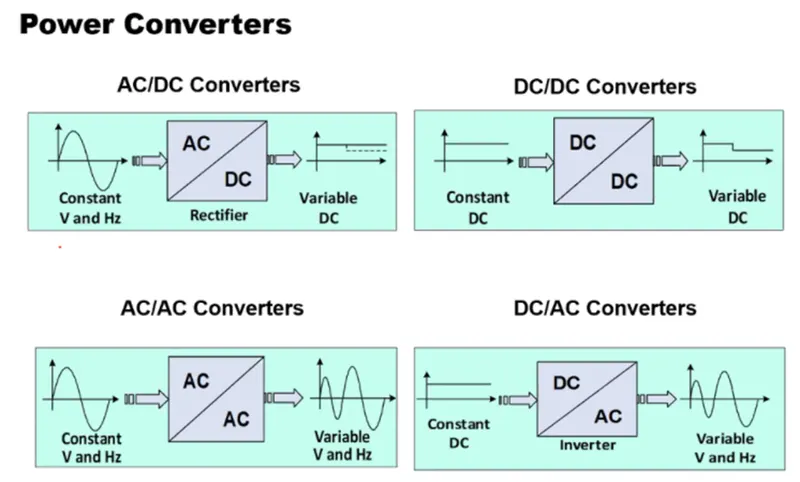
DC-AC converter
It is an inverter which converts DC power from battery to AC power used in an electric vehicle motor.
DC-DC converter
- A DC-DC converter accepts DC input voltage and outputs DC output voltage
- The output of DC to DC can be greater than the input voltage and vice versa. The converter output voltages are used to match the power supply required to the loads
- DC to DC converter circuits consist of transistor or diode switch. Energy storage devices like inductors or capacitors and these converters are generally used as linear voltage regulators or switched mode voltage regulators
- Generally, DC to DC converters can be designed using power semiconductor switching devices and discrete components
AC-AC converter
- AC to AC converters is used for converting the AC waveforms with one particular frequency and magnitude to AC waveform with another frequency at another magnitude.
- We know there are different types of loads that work with different types of power supply like single-phase, three-phase supply, and the supplies can be differentiated based on voltage and frequency range also.
- We require a particular voltage and particular frequency for operating some special devices or machines. For speed control of induction motors, AC to AC converters(cycloconverters) is used majorly.
In HEV and EV except AC to AC converter all other converters are used.
Q2
Ans
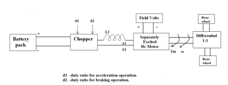
- Rated voltage = 70v
- Duty cycle = 70%
- Supplied voltage for combined motion = 70/100*70 = 50.4v
- Torque equation, T = (V_t*k_phi)/(R_a)-(W_m.((k_phi)^2)/R_a)
- Substituting values
- T = (50.4*0.7)/(0.5)-(W*((0.7)^2)/0.5)---- eq 1
- At steady state condition
- Eq 1 = 24.7 + (0.0051)*w^2
- 70.56-0.98w = 24.7+0.0051w^2
- By rearranging
- 0.0051w^2+0.98w-45.86 = 0
- We get w = 38.91, -231.07
Hence w = 38.91 rad/s.
Q3 develop mathematical model of a DC motor for the following equation in Simulink
W = V/K*phi-Ra/K*phi^2.T
Solution.
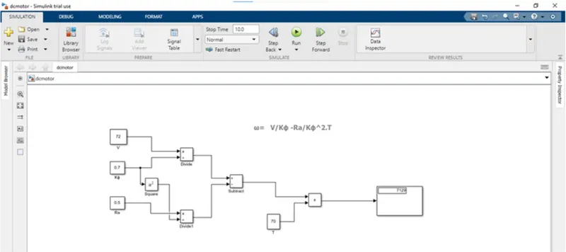
Here we have taken the values for the above equation as
W = V/K*phi-Ra/K*phi^2.T
V = 72v
Ra = 0.5 ohm
Kphi = 0.7v
T = 70
Thus the result is 7129
Q4
Induction versus DC brushless motors by wally rippel, Tesla
Sol-
- In the blog of induction and DC brushless motor, the author has mentioned about positives and negative side of both the induction and DC motor. In the blog, the basic construction of both the induction and DC brushless motor is explained.
- In case of DC brushless motor, permanent magnets are used which produces a rotating magnetic field. This magnetic field when induces a current in the conductor. This current results in force generation in the rotor and this results in rotation of the rotor.
- Whereas in case of induction motor, the current is supplied to the stator which results in the generation of emf, when this emf comes in contact with the rotor which is generally a squirrel cage type, this results in current induced in the rotor. Unlike the DC motor, the rotor consists of conductors plates and placed in a cage-like structure. This also consists of bars around them in which current get induced and the rotor starts rotating.
- One of the main differences is that much less rotor heat is generated with the DC brushless drive. Rotor cooling is easier and peak point efficiency is generally higher for this drive. It is mentioned that the DC brushless can drive at unit power factor, whereas the best power factor for the induction drive is about 85%.
- In case of DC brushless motor, the strength of the magnetic field is adjustable. When at low speed the maximum torque is required magnetic field should be maximum, i.e. inverter and motor current maintained at their lowest optimize efficiency. Whereas there is no such adjustment in case of induction motor.
- As machine size grows, magnetic losses increases proportionally and part load efficiency drops. In case of induction motor, as machine size grows, losses do not necessarily grow.
- The construction of DC brushless motor is costly compared with an induction motor, due to the use of permanent magnets.
- However thought the speed variation of induction motor depends upon the frequency input, it is difficult to control.