Week-6 Challenge: EV Drivetrain
Question 1 : Which types of power converter circuits are employed in electric and hybrid electric vehicle?
Ans:-
Power convertors are 4 types :-
1. AC to DC Converter
2. DC to DC Converter
3. DC to AC Converter
4. AC to AC Converter
1) AC to DC Converter :-
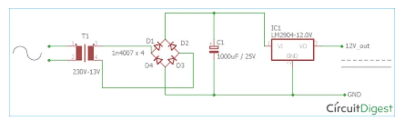
- This type of converter is used in on Board charger and in fast charging station converter.
- This is a Rectifier circuit which is used to convert the Alternating AC Voltage supply to the DC Voltage .
- This is mainly used because there is no readily avilable DC Voltage station.
- Usually the grids are operating in High Voltage AC.
- The OBC Consist of step down transformer, input filter circuit, rectifier circuit and linear voltage circuit.
- The step down transformer is used to reduce the voltage from 230V AC to required voltage of 120V AC or 240V AC.
- Then isoltaor , surge protector and to the input filter circuit for protection of device.
- The output of rectifier circuit is DC of required voltage corresponding to the input AC voltage to the rectifier circuit.
- Then this voltage is used for charging the battery of the vechiles.
2) DC to DC Converter :-
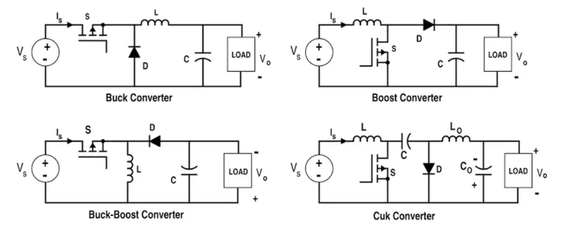
- DC to DC converter are of Buck converter , Boost converter , Buck-Boost converter and Cuk Converter.
- Buck converter is used to reduce the DC of High voltage to low voltage .
- Boost Converter used to increase the DC of low voltage to high voltage.
- Buck-Boost converter is used for both step up and step down of DC Voltage and is more efficient because of using less compoents.
- Cuk is used to reduce the Ripples and Noises from converter.
3) DC to AC Converter :-
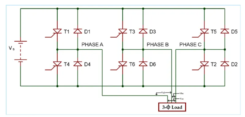
- Genrally DC to 3 Phase AC inverter is used.
- The inverter circuit consist of the filter ( capacitor) in the input side and main bridge is six pair of thyristor and diode.
- The thyristor T1 In ON state is used to pass the positive half cycle and it is TURN OFF and the reverse voltage is protected by diode.
- The thyristor T2 in OFF state is used to pass the negative half cycle an its is TURN OFF and reverse voltage is protected by diode.
- Hence one cycle is produced.
- The thyristor T3, T4, T5 and T6 are switch ON and OFF by controlling the gate supply to produce the AC Voltage cycle with 120 degree phase differnces.
- The gate supply is produced by phase regulator.
- This process is repeated to produce the 3 phase AC supply corresponding to the DC supply.
- Then this voltage is directly applied to the 3 phase load or this voltage is steped by the step up transformer an then supplied 3 phase load.
- The 3 phase supply used in the elctric vechile is the induction motor ( traction motor).
4. AC to AC Converter:-
- This type of converter takes an input AC wave form with a particular voltage and frequency and outputs a different AC wave form with another voltage and frequency.
- The output voltage AND/OR Frequency can be change or maintain depending or the applications.
- This converter has many applications in our daily life .eg. Lamp Dimming , motor speed control.
- There are 4 types of AC to AC Converter.
1. cycloconverter
2. AC to AC Convert DC link.
3. Matrix converter.
4. Hybrid Matrix converter.
Question 2:- An Electric Vehicle's powertrain with 72V battery pack in shown in the diagram below. The duty ratio for acceleration operation is 'd1' and for the braking operation the duty ratio is 'd2'.
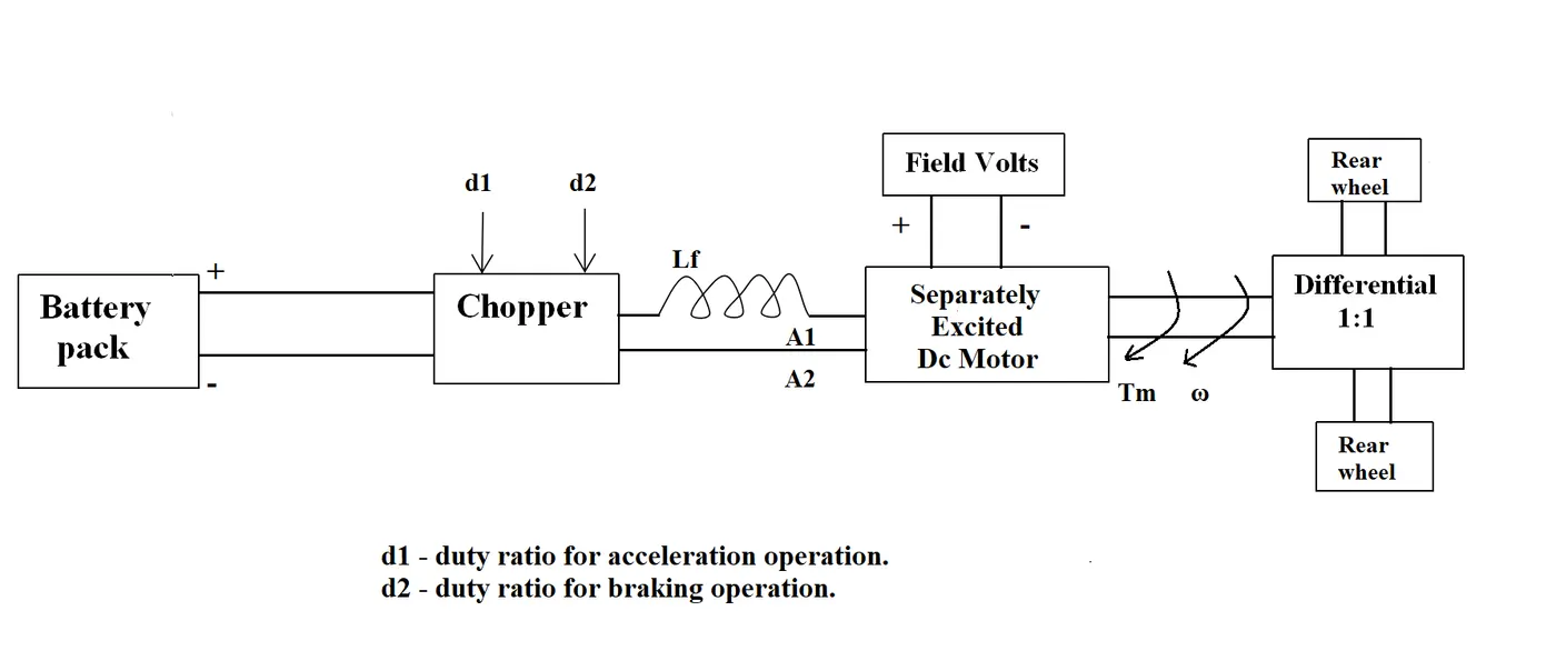
The other parameters of the electric vehicle is given below,
Motor and Controller Parameters:
Rated Armature voltage= 72 V
Rated armature current= 400 A
Ra= 0.5Ω, KΦ= 0.7 Volt second
Chopper Switching frequency= 400 Hz
The vehicle speed-torque characteristics are given by the below equation

What is EV steady state speed if duty cycle is 70%?
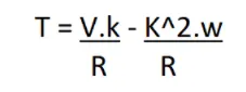
T = Torque
V = Armature Voltage
R = Resistance
w= speed rad/s
compare two equations:-
24.7 + 0.00051*w^2 = ((v*k)/R) - ((k^2)*w/R)
24.7 +0.0051*W^2 = (72*0.7*0.7)/0.5 - (0.7^2/0.5)*w = 24.7+0.0051*w^2
70.56 - 0.98*w = 24.7 + 0.0051*w^2
w^2+ 192.15*w - 8992.15 = 0
in order to find the roots use following formula

as the speed value can not be negative
w = 38.95 rad/ sec
Question 3 :- Develop a mathematical model of a DC Motor for the below equation using Simulink.
ω= V/Kϕ -Ra/Kϕ^2 .T
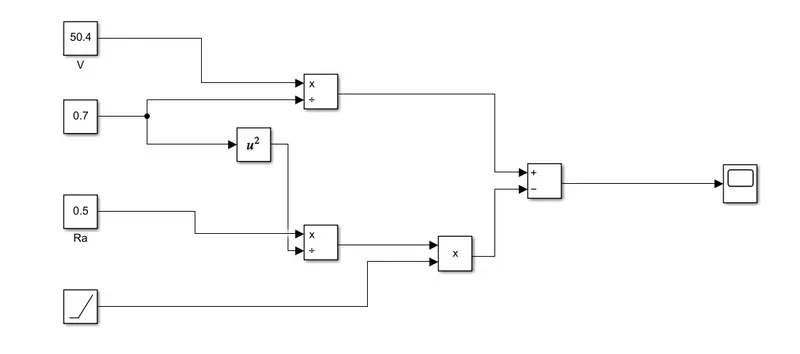
Let us draw a model for the above equation
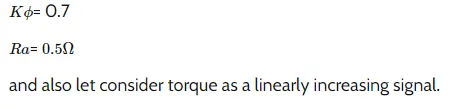
Let V= 50.4 volts
Model :-
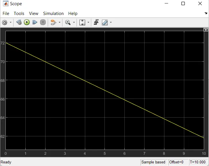
Result :-
Question 4:- Refer to the blog on below topic:
Induction Versus DC brushless motors by Wally Rippel, Tesla
Explain in brief about author’s perspective.
Ans:-
- In the blog of induction and DC brushless motor, the author has Mentioned about positive and negative side of both the induction and DC motor. in the blog , the basics construction of both the induction and DC brushless motor is explained.
- In Case of DC Brushless motor , permant magnets are used which produces a rotating magnetic field . this magnetic field when induces current in the conductor. this current results in force generation in rotor and this results in rotation of the rotor.
- Whereas in case of induction motor, the current is supplied to the stator which results in the generation of EMF , when this emf comes in contact with the rotor which is genrally a squirrel cage type , this result in current induce in the rotor. unlike the DC motor , the consist of conductor plates and placed in cage like structure.this also consist of bars around them in which current gets induce and the rotor start rotating.
- one of the main differnces is that much less rotor heat is generated with the DC brushless drive. rotor cooling is easier and peak point effiency is genrally higher for this drive. it is mentioned that the DC Brushless can drive at unit power factor, whereas the base power factor for the induction drive is about 85%.
- in case of DC brushless motor, the strength of magentic field is adjustable. when at low speed the maximum torque is requied magnetic field should be maximum, ie. inverter and motor current maintain at their lowest optimize efficiency. whereas there is no such adjustment in case of induction motor.
- a machine size grows, magnetic losses increase proportionally and part load efficiency drop. in case of induction motor , at machine size grows , losses necassrily grow.
- The construction of DC brushless motor is costly compared with an induction motor, due to the use of permanet magnets.
- However thought thus speed variation of induction motor depends upon the frequency input, it is difficult to control.
Learning Outcome:-
- Types of converters used in HEV and EV Vechiles.
- To find the velocity using the torque spped expression.
- To get to know about the induction and DC motor and try to find the best option avilable.