Week-6 Challenge: EV Drivetrain
1. Which types of power converter circuits are employed in electric and hybrid electric vehicles?
The EV/HEV/PHEV uses high-capacity batteries such as lithium-ion batteries to power the electric motors, secondary batteries, and various auxiliary loads only by using power converter circuits.
POWER CONVERTER
- They are used to control the flow of power, change the current forms, and voltage levels.
- They generally consist of transistors, capacitors, diodes, electronic switches, controllers, inductors.
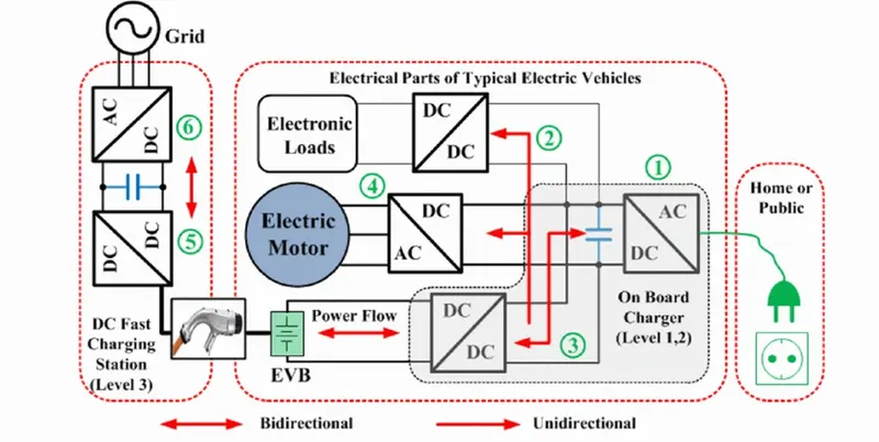 source: google
TYPES OF POWER CONVERTERS
1. EV CHARGER
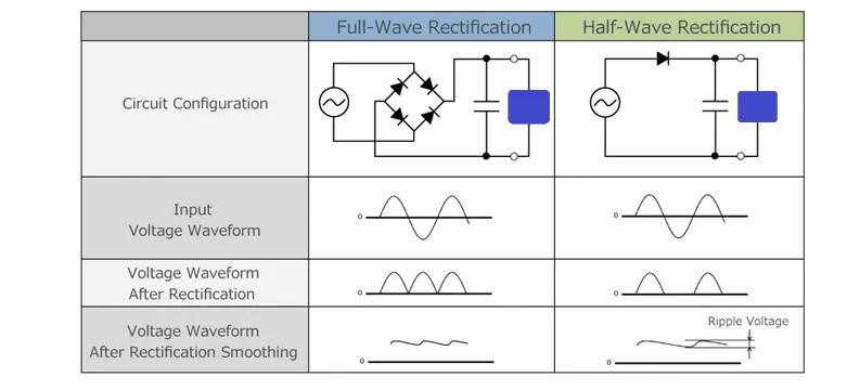
The source from home or grid is an AC source, but the battery requires a DC source to get charged. this can be achieved by converting an AC source to DC by a power converter circuit called a rectifier.
RECTIFIER
- It is used to convert AC to DC.
- they consist of diodes, transformer.
- they use P-N junction diode, which allows current only in forward bias and blocks in reverse bias (allows only in one direction)
- they are divided into half-wave and full-wave rectifiers.
HALF-WAVE RECTIFIER
- They use a single diode
- rectifies only half signal ie, only positive half cycle is rectified and the negative half cycle is blocked, and the other way.
FULL-WAVE RECTIFIER
- They use more diodes.
- full AC input signal is converted to DC output ie, both positive and negative half cycle of AC is rectified to DC output.
- Efficiency is more than half-wave rectifier.
 source: google
2. EV MOTOR DRIVE
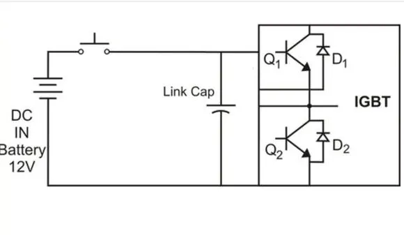
The recent EV uses an AC induction motor which requires AC input, but the output from the battery is DC. In order to convert DC from the battery to AC, a power converter circuit called inverter is used.
INVERTER
- They are used to convert DC to AC.
- they consist of transistors ( mostly IGBT), diodes, controllers, transformers.
- the path of the current in the circuit is controlled by the opening and closing of switches, producing AC from DC.
- mostly the pulsating pattern is used in EV by the pulse width modulator.
- they can be classified according to their input source(voltage/current), waveforms(square/quasi square/pulse width modulated) and connections(series/parallel/bridge).
 source: google
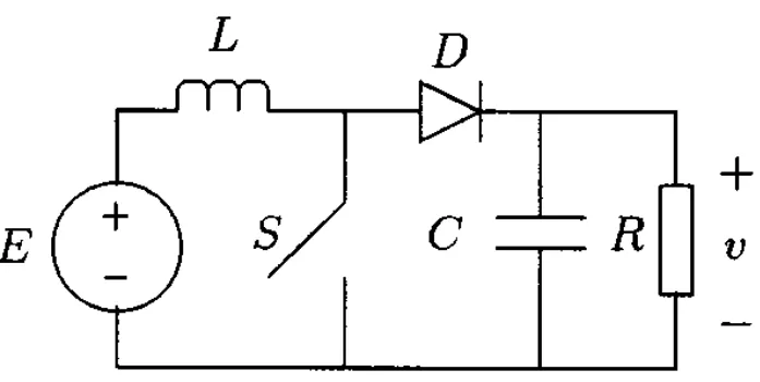
3. DC-DC CONVERTER
- It is used step up or step down the power.
- they consist of diodes, switching devices, capacitors, inductors.
- when an EV with a DC motor requires more voltage then step-up/boost converter is used. for example, DC (400V) from a battery is boosted to DC (600V) for a DC motor.
- the secondary battery and auxiliary load require less voltage from a high-capacity battery. it is achieved by a DC-DC converter.
- a step-down/buck converter is used to reduce the high voltage to a low voltage level. for example, 48V from HEV battery is reduced to 14V and supplied to the secondary battery and auxiliary loads.
 source: google
2. AIM
- To find the EV steady-state speed for the duty cycle of 70% with the given parameters
INPUT
voltage _battery V_bat =72 V
armature current I_a = 400 A
Armature resistance R_a = 0.5 ohm
motor constant k(pfi) = 0.7
chopper switchin frequency = 400 Hz
The given vehicle speed-torque characteristics eqn
`T_v = 24.7 + (0.0051)ω^2`---------------------eqn 1
CALCULATION
The motor torque speed characteristics eqn,
`ω = V/(kφ)-(R_a)/(Kφ)^2*T`
`ω = (V*Kφ - R_a*T)/(Kφ)^2`
`ω*(Kφ)^2 =V*Kφ - R_a *T`
by solving the abv eqn
`T = (V*Kφ)/R_a - (ω*(kφ)^2)/R_a`---------------main eqn
to find the V,
V_bat * duty cycle = V
V = 72 * 70%
= 72 * 0.7
V = 50.4
substituting in main eqn,
T = (50.4 * 0.7 )/ 0.5 - ω * (0.7)^2/0.5
T = 35.28/0.5 - (ω * 0.49) / 0.5
T = 70.56 - (0.98) ω ------------------------------------eqn 2
equating eqn 1 and 2,
24.7 + (0.0051) ω^2 = 70.56 - (0.98) ω
0.0051 ω^2 + 0.98 ω = 70.56 -24.7
0.0051 ω^2 + 0.98 ω - 45.86 = 0 ----------------------------eqn 3 (quadratic equation)
here
a = 0.0051
b = 0.98
c = -45.86
substituting `x = -b +- root o((b^2 -4ac)) /(2a)`
`ω = (-0.98 +- 1.3767 ) / 0.0102`
ω = 38.9 or - 231 rad/sec
ω = 38.9 rad/sec
The EV steady-state speed for the duty cycle of 70% with the given parameters is ω = 38.9 rad/sec
RESULTS
- Thus the EV steady-state speed for the duty cycle of 70% with the given parameters is calculated.
3. AIM
-
To develop a mathematical model of a DC Motor for the below equation using Simulink.
TORQUE-SPEED CHARACTERISTIC EQUATION
`ω = V/(kφ) - (R_a/(kφ)^2)*T`
SIMULINK MODEL
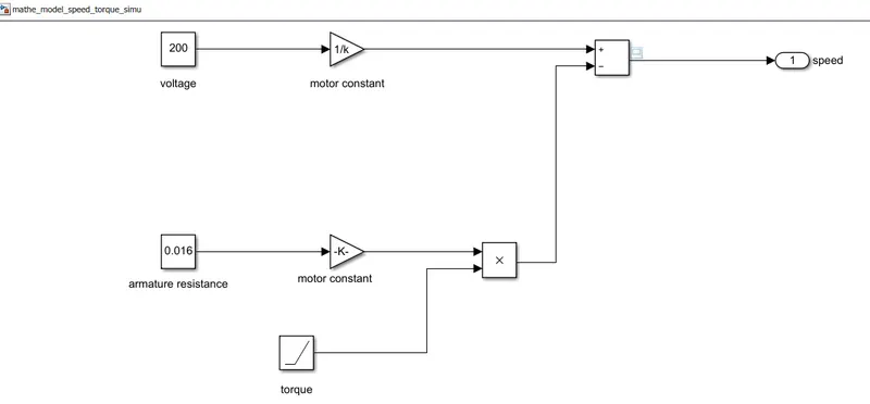
- voltage is given by constant block V=200
- Armature resistance is given by constant block R_a = 0.016
- Torque (T) is varied from 0 to 10 sec (stop time = 10.0 sec) by ramp block
- motor constant k = 0.5, is given to gain block from the base workspace by entering in the command window.
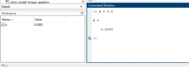
- scope viewer is selected through connect to viewer.
- the output is given to the outport speed.
OUTPUT
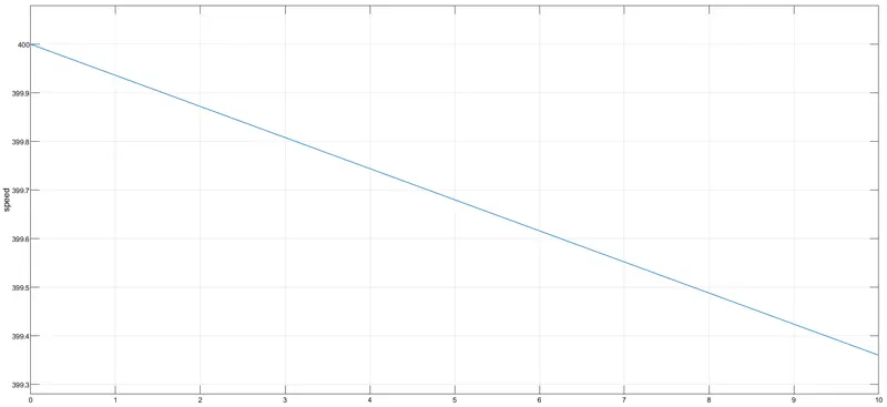
- the speed (y-axis) decreases with an increase in torque (x-axis).
RESULT
- Thus the mathematical model of a DC Motor for the torque-speed equation using Simulink is developed and output is plotted.
Google drive link - https://drive.google.com/file/d/1tx_XpeWj1vBzh38tSNtiHI9Ck_7usFJ3/view?usp=sharing
4. Induction VS DC brushless motors by Wally Rippel, Tesla. Explain in brief the author’s perspective.
The author discusses DC brushless and induction motors. he thinks that the already replaced lithium-ion battery, DC brushless motor, or induction motor would become obsolete, or else there will be stability maintained over coming decades.
He then explains about DC brushless motor,
- the rotor consists of two or more permanent magnets which produce a magnetic field.
- the stator core is a thin, stacked lamination with windings where the current flows.
- as the rotor rotates with varying stator current, the conversion of electrical to mechanical energy occurs.
- the current is controlled by an inverter, without an inverter, DC brushless motor would be useless.
In his explanation on the Induction motor,
- the stator appears the same as DC brushless, but the rotor arrangement differs. it does not have a magnet, instead, steal lamination with conductors.
- the speed of the rotor can be controlled by the frequency of AC.
- they do not need an inverter and the torque is produced at the outset although they have great utility, the torque performance is less when compared to DCBL. and with the addition of inverter with feedback loops, can achieve the same performance.
Similarities and Differences,
- both have similar stators, and 3 phase modulating inverters.
- differences are rotor and inverter controls
- DC Brushless requires a position sensor, where the induction requires a speed sensor
- the peak point energy efficiency of DC brushless drive is higher than induction drive, while the average energy efficiency is opposite.
- the magnetic field strength of magnets in brushless DC motor cannot be easily adjusted in order to reduce the losses and increase efficiency, but with no magnets in induction motor, the magnetic field strength can be adjusted, and by adding smart inverter it has more advantages than DC Brushless motor
finally, he conclude that DC brushless motor will be an advantage for HEV/PHEV. the induction motor will be an advantage for pure EV. and both will work along in the coming future of EV/HEV/PHEV.