Week-6 Challenge: EV Drivetrain
Aim:
- To identify the types of power converter circuits employed in electric and hybrid electric vehicle.
- To claculate the steady state speed of an ev with given inputs if duty cycle is 70%.
- To devolpe a mathmatical model of DC motor.
- Refer to the blog and explain in brief about author's perspective.
Study -1
Power Electroinc Converters:
In Electric and Hybrid Vehicle (EV/HEV),the power electric converter are considered as the key element that interface their power sourecs to the drivetrain of the EV's power system ,advenced DC/DC and DC/AC converter are requried to adapt the output voltage and current levels with high power quality.
The 3 types of converters which are widely used in an Electric Vehicle are:
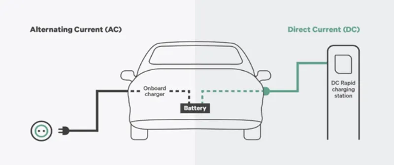
AC - AC Conveter (On Board Charger):
AC to DC coverters are most commomly used in pulg-in Hybrid Electric Vehicle get their propulsion power from an external electricity sources (charging stations) which is alternating current. The battery needs to be charged using a direct current sources.For this purpose ,AC to DC converter is employed in a PHEV $ PEV.
DC - DC Converter:
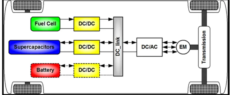
DC -DC converter can be used to interface the elements in the electric power trian by boosting or chopping the voltage levels. By introducing DC/DC conerters one can choose the voltage variation of the devices and the power of each device can be controlled. The power of the vehicle such as top speed, acceleration time from 0 to 100 Km/h,Weight, maximum torque, and power, continuous power).
DC - AC Converter (Inverter):
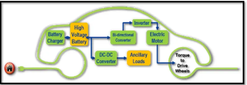
The DC/AC converter is required to convert the dc power to a suitable ac power for the electric machine.
The power output from battery pack (DC current) is converted using inverter to be used in electric motor (AC current).
Study -2
EV with given inputs if duty cycle is 70%:
The other parameter of the electric vehicle is given below.
motor and controlled parameters:
Rated Armature voltage=72 V
Rated Armature current=400 A
Ra =0.5Ω, Kɸ=0.7 Volt second
Chopper Switching frequency=400Hz
The Vehicle speed - torque charecteristics are given by the below equation
Tʋ=24.7+(0.0051)w^2
What is EV steady state speed if duty cycle is 70%?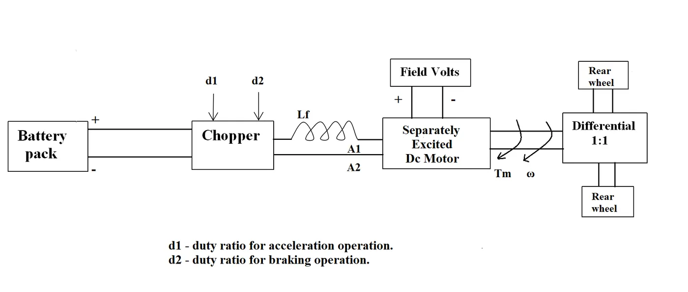
given:
The following input parameter are given:
Battery pack voltage (v)=72 V
Rated armature current =400 A
Armature Resistance(Ra)=0.5Ω
Motor contant (kɸ)=0.7
Chopper Switching frequency =400 Hz
Duty Cycle=70%
solution:
vehicle Ouput voltage (V)is given by:
v=Battery voltage (v)* Duty cycle
v=72 *0.70
Thus , vehicle voltage =50.4v
now ,equation for vehicle torque is given by:
Tʋ =(Vʋ-ω.Kɸ).Kɸ/Ra
where ;
Tʋ=vehicle Torque (N-m)
Vʋ=vehicle voltage (volts)
ω=Steady state speed of vehicle (rps)
Kɸ=Motor constant
Ra= Armature Resistance
Substituting all these values in equation ,we get
Tʋ=(50.04-0.7.ω).0.7/0.5
=70.56-0.98.ω
=24.7+0.0051.ω2
Solving these two equations,
70.56-0.98 .ω=24.7+0.0051.ω2
we get a quadratic equation ,we get two values of;
ω=38.85 rad/s and
ω=-230.95 rad/s
we take the positive value;
Study -3
To Develop a mathematical model of a DC Motor:
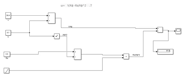
v=50.4volts
k=0.7
Ra=0.5ohms
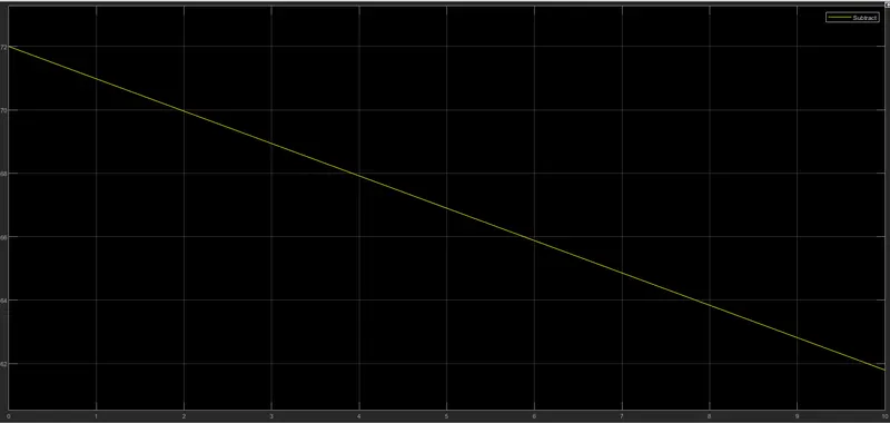
The scope of speed of motor as shown in below:
Study-4
Refer to the blog on below topic:
Induction Versue DC brushless motor by wally Ripple,Tesla
Explain in brief about author's perspective.
The brushless machines, the rotor includes two or more permanent magnets that generate a DC magnetic field .In turn, this magnetic field enters the stator core and interacts with current flowing within the winding to produce a torque interaction between the rotor and stator.As the rotor rotates,it is necessary that the magnitude and polarity of the stator current be continously varied and in just the right way such that the torque remains constant and the conversion of electrical to machanical energy is optimally efficient.
Unlike the DC brushless rotor, the induction rotor has no magnets – just stacked steel laminations with buried peripheral conductors that form a “shorted structure.” Currents flowing in the stator windings produce a rotating magnetic field that enters the rotor. In turn, the frequency of this magnetic field as “seen” by the rotor is equal to the difference between the applied electrical frequency and the rotational “frequency” of the rotor itself. Accordingly, an induced voltage exists across the shorted structure that is proportionate to this speed difference between the rotor and electrical frequency. In response to this voltage, currents are produced within the rotor conductors that are approximately proportionate to the voltage, hence the speed difference. Finally, these currents interact with the original magnetic field to produce forces – a component of which is the desired rotor torque.
Both DC brushless and induction drives use motors having similar stators. Both drives use 3-phase modulating inverters. The only differences are the rotors and the inverter controls. And with digital controllers, the only control differences are with control code. (DC brushless drives require an absolute position sensor, while induction drives require only a speed sensor; these differences are relatively small.)
One of the main differences is that much less rotor heat is generated with the DC brushless drive. Rotor cooling is easier and peak point efficiency is generally higher for this drive.