Week-6 Challenge: EV Drivetrain
EV DRIVETRAIN
1: Which types of power converter circuits are employed in electric and hybrid electric vehicles?
ANSWER : Actually there are four types of power converters in use today, AC-AC converters, AC-DC converters, DC-DC converters and DC-AC converters. Out of these four, the AC-DC, DC-DC and DC-AC converters are mainly used in electric and hybrid electric vehicles.
AC-AC Converter - These are used to alter the voltage or frequency of an AC power supply in order to meet the user demands. AC-AC converters are typically seen in household electronics which use low frequency AC current power supply.
AC-DC converters(Rectifier) : AC-DC converters are electrical circuits that transform alternating current (AC) input into direct current (DC) output. As most electronic appliances require DC supply and only AC current is available through the power grid lines, these converters are in wide use now. In the case of EV and HEV, these converters are mainly used to charge the battery from the electric grid. These converters will either be present on the charging cable system or inside the car. It takes AC supply from the outlet, converts it by altering the sine wave using rectifiers and then stores the power in DC form in the battery.
DC-DC converters : A DC-to-DC converter is an electronic circuit or electromechanical device that converts a source of direct current (DC) from one voltage level to another. They are also mentioned as choppers. These are usually used in electronic devices with a DC battery power supply. As the battery can only supply current at specific voltage and different circuits in the device need different voltage supply, these converters are used either to step up or step down the battery power according to the needs. In EV and HEV too DC-DC converters are used in the similar context. As the different auxiliary units in a car need different levels of voltages for operation, these converters are used to meet these demands from the battery.
DC-AC converters(Inverter) : An inverter is a power electronic device or circuitry that changes direct current (DC) to alternating current (AC). The best example are the home inverters we use at home, which supplies us with AC current by converting the DC power from a battery during power cuts. In EV and HEV, these are generally used inorder to supply power to the AC motor from the battery. The inverter converts energy from the high-voltage battery to multiphase AC current to drive the traction motor, which is a 3-phase inductive load. Electronics in the inverter control this power conversion to the traction motor with highest possible efficiency and reliability.
------------------------------------------------------------------------------------------------------------------------------------
2. Steady state speed calculation
AIM: Calculate the EV steady state speed when the duty cycle is 70%
OBJECTIVE: First calculate the output voltage with duty cycle, then substitute the values in the DC motor equation and solve it using the given characteristic equation.
Given values,
Battery Voltage, V = 72V
Armature Current, I = 400A
Ra = 0.5 ohm
`Kphi` = 0.7 Volt second
Frequency, f = 400Hz
The vehicle speed-torque characteristics are given by the below equation
`Tv = 24.7 + 0.0051omega^2`
EQUATION
`omega = (V/(kphi) - (Ra)/(kphi)^2)*T`
SOLUTION
Battery Voltage, Vb = 72V
Duty cycle = 70%
Therefore, Output Voltage, V = 72 * (70/100) = 50.4V
We have the equation
`omega = (V/(kphi) - (Ra)/(kphi)^2)*T`
Rearranging the equation,
`T = (V*(kphi))/(Ra) - ((kphi)^2*omega)/(Ra)`
Substituting values
`T = (50.4 * 0.7)/0.5 - ((0.7^2)omega)/0.5`
`T = 70.56 - 0.98*omega` -------(1)
We know that,
`Tv = 24.7 + 0.0051*omega^2` --------(2)
At steady state, T = Tv
Therefore, equating and solving equations (1) and (2)
We get,
`omega = 38.915`rad/sec
CONCLUSION
The steady state speed at 70% duty cycle is 38.915 rad/sec or 371.61rpm.
--------------------------------------------------------------------------------------------------------------------------------------
3. Mathematical model of a DC Motor.
AIM: To develop a mathematical model of a DC Motor for the below equation using Simulink.
`omega = (V/(Kphi) - (Ra)/(kphi)^2) * T`
OBJECTIVES: To develop the given equation into derivative form so as to make a mathematical model. Then use basic simulink blocks to make a model which calculates the speed, torque and total current in a DC motor.
EQUATIONS:
Consider the given Dc motor model,
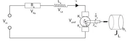
Using kirchhoff's law,
Vin - VRa - VLa - Vemf = 0
Also we know,
VRa = ia*Ra
VLa = La* dia/dt
Vemf = Ke*d(theta)/dt
Where,
ia = Armature current
Ra = Armature resistance
La = Inductance
Ke = back emf constant
Substituting in the eqn
Vin - iaRa - La* dia/dt - Ke*d(theta)/dt = 0
Rearranging and forming an Differential Voltage Equation,
`(dia)/dt = 1/(La) *(text(Vin)- (ia*Ra) - Ke*(d(theta))/dt)` ------------(1)
Similarly using Newton’s Law,
Te - Ttheta - Tb - TL = 0
Te = electromagnetic torque
T(theta) = torque generated from the rotational acceleration of the motor
Tb = torque due to friction and angular velocity in the motor
TL = torque generated by the load
Also we know,
Te = Kt*ia
Ttheta = Jm*d^2(theta)/dt^2
Tb = bm* d(theta)/dt
Where,
Kt = torque constant
Jm = inertia of motor
bm = damping factor
Substituting in the eqn
Kt*ia - Jm*d^2(theta)/dt^2 - bm*d(theta)/dt - TL = 0
Rearranging,
`(D^2(theta))/dt^2 = 1/(Jm)*(Kt*ia - bm*(d(theta))/dt)` --------------------(2)
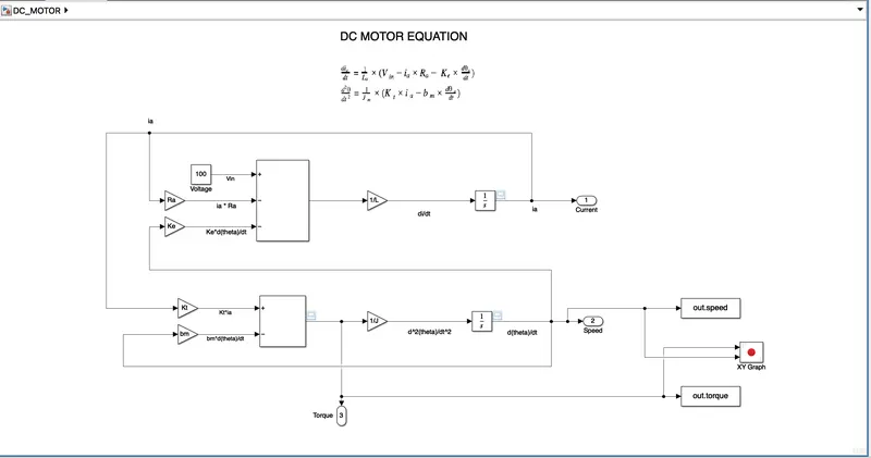
Modeling in simulink using eqns(1) and (2)
MODEL
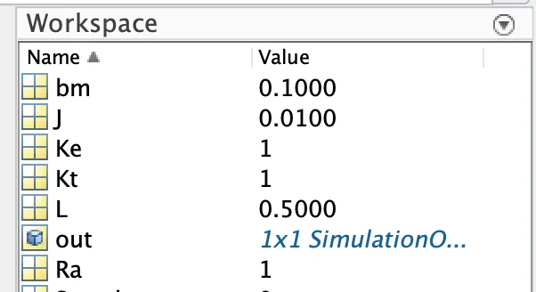
Parameters defined in matlab workspace
Blocks Used:
- Gain
- Integrator
- Constant
- Add
- Outport
- Scope
- To workspace
- XY Graph
RESULTS
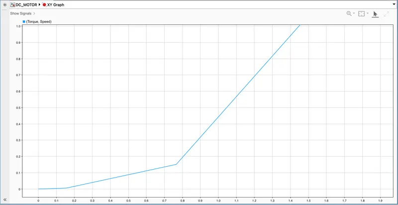
The resulting figure shows values of Current, Speed and Torque plotted against time.
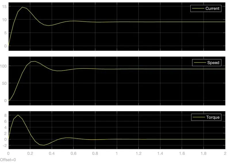
The XY graph shows torque plotted against speed.
CONCLUSION
Mathematical model of the DC motor is successfully developed.
--------------------------------------------------------------------------------------------------------------------------------------
4. Induction Versus DC Brushless Motors
The author Wally Rippel is analysing the application of DCBMs and Induction motors in the article published in tesla’s blog.Wally Rippel is an engineer with a long history in the EV industry, whose words clearly reflect the passion he has for the field.
He starts by establishing that one single type of motor won’t be able to meet the requirements of the industry and proves the point by discussing the diversity in IC engines. He then states that even though the EV industry has seen a lot of changes in the past decades, the DCBMs and induction motors will be in use for many years to come.
Wally then proceeds to explain the basic differences in the two technologies. According to the author, in DCBMs the rotor consists of permanent magnets which produce a magnetic field in the laminations of the stator and the interaction between this field and the current in the stator produces the rotating torque. He also mentions that for this to work efficiently the magnitude and polarity of the stator current needs to be varied continuously. This needs to be done in the correct manner to obtain maximum efficiency. Inverters are used for this purpose.
And in the case of induction motors, the rotor has no magnets instead it’s made up of stacked steel laminations with buried peripheral conductors. The author mentions this setup as a ‘shorted structure’. The stator arrangement is basically the same as the DCBMs. When current passes through the stator it produces a rotating magnetic field which enters the rotor and the induced voltage in it will produce currents within the rotor with proportion to the voltage. Finally these currents interact with the stator magnetic fields to produce the desired rotor torque.
Then the author compares the two in their source of input. Induction motors have the ability to start under load when connected to utility 3 - phase power outlets without the support of an inverter. This was one of the main reasons for their success.
This also comes as a limitation because it can directly work only with AC power supply. In contrast, a brushless DC motor produces no starting torque when directly connected to fixed frequency utility power. They really need the aid of an inverter whose “phase” is maintained in step with the angular position of the rotor.
He then mentions how an inverter connected to an induction motor can make it work with DC supply and also how feedback loops in it can improve the performance and compatibility when considered for vehicle application, thus giving it a chance to compete with DC motors.
Author then goes deep into the comparison and lists out the various advantages and disadvantages of both the motors. One of the main differences is that much less rotor heat is generated with the DC brushless drive. Rotor cooling is easier and peak point efficiency is generally higher for this drive. The DC brushless drive can also operate at unity power factor, whereas the best power factor for the induction drive is about 85 percent. This means that the peak point energy efficiency for a DC brushless drive will typically be a few percentage points higher than for an induction drive.
Another main difference comes in the controlling of the magnetic fields. As DCBMs have permanent magnets, their field cannot be controlled. While in induction motors it can be controlled. The fields are given maximum when the max torque is required at low speeds to reduce the inverter and motor currents to a minimum inorder to reduce the I^2*R losses, thus improving efficiency. This needs to be done the other way too, like when the torque requirements are low the magnetic fields need to be kept at low to reduce eddy and hysteresis losses. This feature clearly gives an edge over the permanent magnet DC motors.
Next the author compares the effect of size in these motors. With DC brushless, as machine size grows, the magnetic losses increase proportionately and part load efficiency drops. With induction, as machine size grows, losses do not necessarily grow. Thus, induction drives may be the favored approach where high-performance is desired; peak efficiency will be a little less than with DC brushless, but average efficiency may actually be better.He also points out that the use of permanent magnets in the DC motor makes it more expensive too.
Author then ends the comparison with a last point of ease to control. As Induction motor laws are more complex and difficult to understand they are more difficult to control over the torque-speed range.
Wally then states that, ‘DC brushless drives will likely continue to dominate in the hybrid and coming plug-in hybrid markets, and that induction drives will likely maintain dominance for the high-performance pure electrics’ as his conclusion to the article. He also raises a question of what will happen as HEV becomes more electrically intensive and as their performance levels increase. He finishes off by stating that we will be seeing both the motors working close by close in the coming golden era of HEVs and EVs.
--------------------------------------------------------------------------------------------------------------------------------------