Week -2
1.DOORBELL USING SOLENOID BLOCK
REPORT
AIM: To make a Simulink model of a Doorbell using solenoid block.
OBJECTIVE: To create a simulation with a solenoid block that activates with an interval of 2 seconds as the arm hitting the bell would do.
BLOCKS USED:
- Pulse Generator
- Simulink-PS Converter
- Switch
- Battery
- Electrical Reference
- Solver Configuration
- Solenoid
- Ideal Translational Motion Sensor
- PS-Simulink Converter
- Mechanical Translational Reference
- Scope
SIMULATION
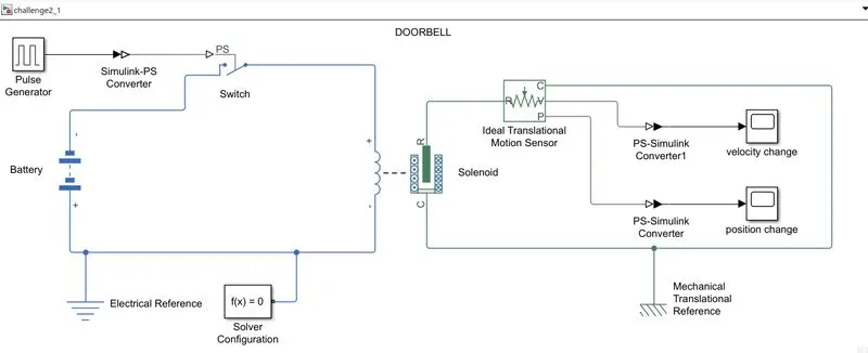
EXPLANATION:
A Pulse Generator block is used to create the 2-second gap signal to the switch block. The switch block closes the circuit with respect to this input and gives electricity to the solenoid block thus activating it. A battery block is used as the electricity source. An electrical reference block is also added to the circuit. The motion in the solenoid block is sensed by an Ideal Translational Motion Sensor block which captures the change in velocity and position. These results are then plotted against time using scope blocks. A mechanical Translational Reference is also added connected as reference for the sensor.
RESULTS:
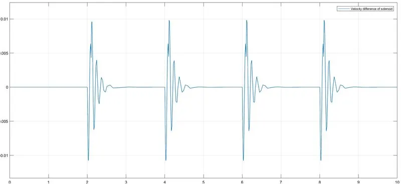
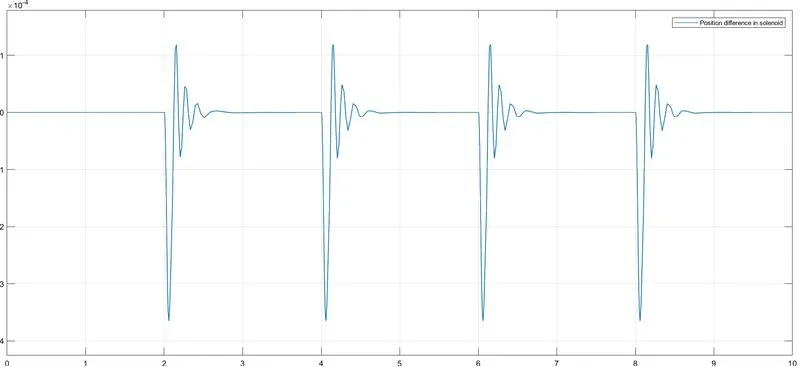
The above plots show the velocity and position changes in the solenoid in an interval of two seconds. Therefore an arm attached to this solenoid block will hit the bell in the given conditions. The Simulink model is attached below.
CONCLUSION:
The simulation of the doorbell using a solenoid block was successfully made and the movement of the plunger(solenoid) was observed.
2.THERMISTOR
REPORT
AIM: To use a thermistor to sense the temperature of a heater & turn on or turn off the fan.
OBJECTIVE: The temperature source in the simulation must give 20C for the first 10 seconds, 27C for the next 20 seconds, and 23C for the last 20 seconds. The fan should be switched ON whenever the temperature goes above 25C.
Condition: Input - 0 to 10 sec temp is 20 °C
10 to 30-sec temp is 27 °C
30 to 50-sec temp is 23 °C
Output - Fan should be ON only > 25 °C
else OFF
THERMISTOR: A thermistor is a semiconductor that has a resistance capacity more than a conducting material and less than insulating material. Its electrical resistance varies with the change in the temperature or thermally sensitive resistor.
BLOCKS USED:
- Signal Builder
- Controlled Temperature Source
- Thermal Reference
- Thermistor
- Battery
- Solver Configuration
- Electrical Reference
- Resistor
- Voltage Sensor
- PS-Simulink Converter
- Switch
- Constant
- Simulink-PS Converter
- Controlled Voltage Source
- DC Motor
- Mechanical Rotational Reference
- Ideal Rotational Motion Sensor
- Scope
SIMULATION
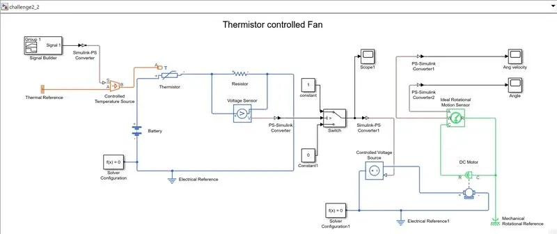
EXPLANATION:
A controlled temperature source block is used to regulate the temperature for the simulation. A signal builder block is used to create the input for the heat source block with the given conditions. A thermal Reference block is connected to the temperature block for reference. The Thermistor takes this temperature as the input and varies the current flowing through the circuit by creating differences in the resistance.
A battery block is used to power the circuit. The change in resistance is sensed by measuring the change in voltage using a voltage sensor block connected parallel to a resistor block.
These voltage variations are then passed through a switch that compares the voltage value to a predetermined value(voltage for 25C). If the condition is satisfied the switch passes a constant value of 1 and if not then 0.
This constant value is then converted to a physical signal and passed to a controlled voltage source block that takes this value and maintains the corresponding value as voltage throughout the circuit. That is if the value 1 is passed to the block, 1V of voltage will be generated, and for the value 0, no voltage.
This voltage is then used to run a DC motor block(fan). The angle and angular velocity, i,e whether it is ON or OFF, is measured by using an ideal rotational motion sensor block. These values are the plotted against time using scope blocks.
RESULTS:
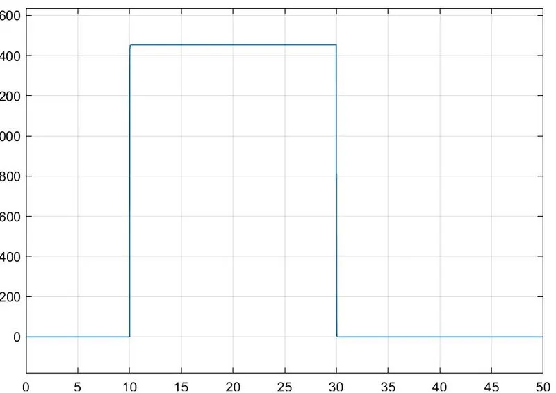
Plot shows motor running from seconds 10 to 30 where the temperature is above 25C.
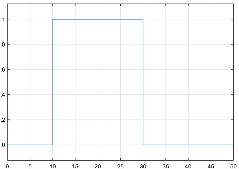
Plot shows the output from the swuitch where value 1 is only between seconds 10 to 30.
Thus the motor operates when the themperature is above 25C and is OFF otherwise. Therefore a fan connected to the motor would give us the required output. The Simulink model is attached below.
CONCLUSION:
The simulation where a fan is switched ON whenever the temperature goes above 25C is successfully created.