Week-6 Challenge: EV Drivetrain
Question 1.
POWER CONVERTERS
As seen in the nomenclature, power converters are semiconductor application to change the magnitude or waveform of the input signal, designed for high voltage and currents. Because of its ability to control the input signal, its usage is inevitable in almost all the electrical apllication. The type of power converter used depends on the functioning required.
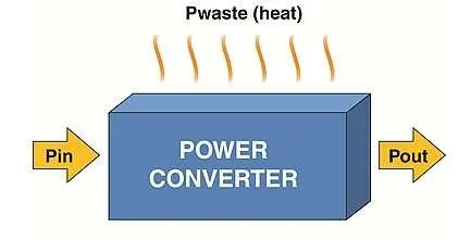
In hybrid and electric vehicles, the application of power converters can be switching action over an interval of time, or converting alternating currents to direct current, or converting direct current into alternating current. or converting direct current into direct current of different voltage levels or operating a dc motor in different modes - forward motoring, forward brake, reverse motoring or reverse braking etc.
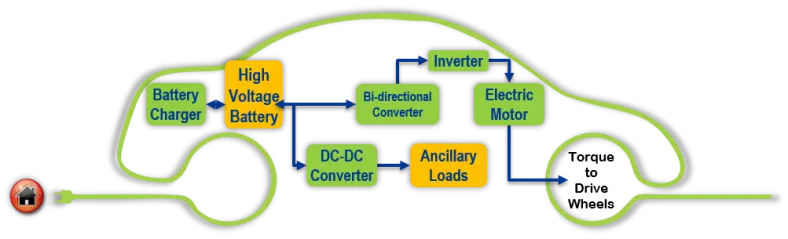
In hybrid and electric vehicles, three types of power converters used are:
1. AC-DC converters
2. DC-AC converters
3. DC-DC converters
1. AC-DC converters
Also known as rectifiers are used to convert ac input into a dc waveform. It can be single phase rectifier or 3 phase rectifier. The rectification process can be fixed or controlled type using power diode or thyristor respectively. The application of rectifier can be ac charging of PLUG IN HYBRID VEHICLES and the electric vehicles.
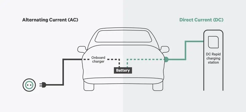
DC-AC CONVERTER
Also known as inverter, is used to convert dc input into alternating current output. It can be single phase inverter or 3 phase inverter. It is mainly used in powering the induction motor or the stator of dc motor through battery current.
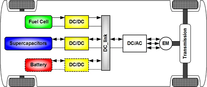
3. DC-DC converter
This type of power converter converts a dc input into a dc but with different magnitude of voltage and current or a changed waveform. They might be used as a chopper circuit or as a clamper or a clipper circuit. They can vary the average output voltage from the input voltage as per the local requirement. They can be used to connect together components,working at different voltage levels.
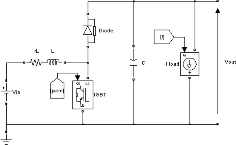
The above circuit shows the circuit diagram of DC- DC converter. Here the output voltage depends on the DUTY CYCLE of the IGBT.
Question 2.
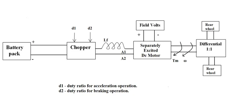
In the given arrangement
Working
The battery pack provides a continous voltage of 72 volts in its output terminal. which passes through chopper. The chopper takes acceleration pedal and brake pedal as input. A four quadrant chopper works in forward motoring mode, forward braking mode, reverse motoring mode and reverse braking mode. The acceleration pedal contributes for motoring mode whereas the brake pedal contributes for regenerative braking mode. The acceleration pedal and brake pedal values are in angles pressed by the driver, depending on the driving condition. Equivalent numbers are provided to these input accelerator and brake signals. Depending upon the intensity and drive cycle of the brake and acelerator, the voltage to armature of the dc motor changes which furthur changes the speed of vehicle.
Here d1 is the drive cycle of acceleration switch and d2 is the drive cycle of braking switch. During motoring mode acceleration switch is activated. If an ideal wide open throttle condition is considered, the average voltage output of the chopper is
V battery*(T on/ T)
where V battery is the output voltage of the battery and T on/ T is the duty cycle of the acceleration operation ie d1. Vt is the terminal voltage to motor.
Vt = V battery * d1 volts
during braking mode the run the motor in regerative mode , considering full brake is applied
Vt = V battery * (1-d2) volts as the vehicle runs for duty cycle 1-d2
In this question.
We consider a simple braking instead of regenerative braking. The vehicle is assumed to be running in only 2 conditions motoring and braking mode. Hence we see d2=1-d1.
The motor recieves battery supply in only motoring mode. Hence we get the motor terminal voltage
Vt= V battery * d1.
The motor speed torque equation is:
N = Vt/(K`phi`)- Ra / (K`phi`)^2 * T
Where N is the speed of motor in rpm, K is motor constant, `phi` is the maximum flux, Ra is the armature restistance and T is the torque produced by the motor. The speed torque equation of the vehicle is

where`omega` is the speed of vehicle in rpm and Tv is the required torque.
Calculation
Given
battery voltage =725 volts
Ra=0.5, K*`phi`=0.7 volts second
d1=0.7.
From the above equations, we get.
Vt = 72 * 0.7 = 50.4 volts
N = 50.4/0.7 - 0.5/0.7^2 * T
N = 72 - 1.0204 * T
N = 72 - 1.0204*(24.7 + 0.0051)* N^2
0.0052* N ^2 + N - 46.796 = 0
solving the above quadratic equation using sridharacharya formula and allowing only the positive value of speed we get
N = 38.917 rpm
The steady state speed of the vehicle provided differential ratio 1:1 is 38.917 * 1 = 38.917 rpm.
Question 3
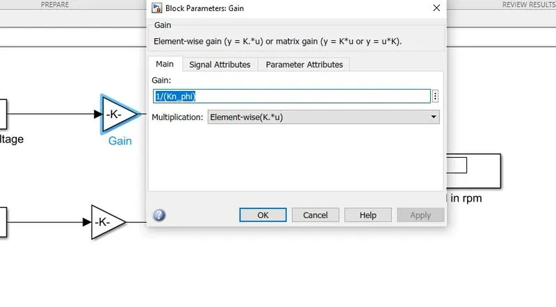
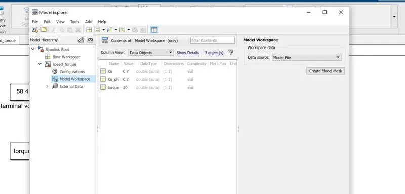
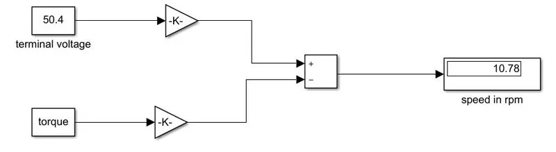
Aim: To develop mathematical model of a dc motor for the given equation using simulink
ω= V/(Kϕ) -Ra/(Kϕ)^2 .T
Model:
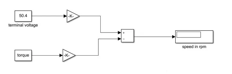
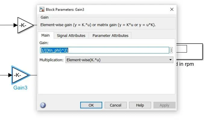
OUTPUT
Question 4
About the authur
The author Wally Rippel is a ' long time proponent of electric vehicles'. He has worked as an engineer in Aero Vironment, where he helped to devlop EV1 for general motors. He was also featured in the documentary " who killed Electric car". He has also worked for Jet Propulsion Laboratory on electric vehicles battery research. In 1968, as a caltech undergraduate student he build an electric car. It was a converted 1958 Volkswagen microbus. He won the GREAT TRANSCONTINENTAL ELECTRIC CAR RACE against MIT.
IDEA OF THE TEXT
The present context focuses on the differences between brushless DC motor and induction motor, based on various factors. They will be discussed in details. Also a basic overview of each of these motors is presented, with the idea of which one is better. But the question never was that, as wally writes "There is no one best engine type, rather there are different types of engines to suit personal requirements, such as price and performance. This is also true for electric vehicle drives."
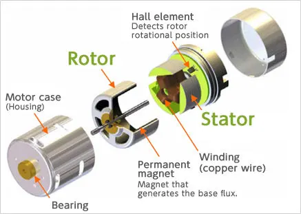
DC BRUSHLESS MACHINE.
As the name suggests, here the brushes are replaced with some technology. The rotor of these motors consists of 2 or more permanent magnets. These magnets produces flux. These electric field enters the dc motors's stator winding through which alternating currents flows. The current carrying conductor when placed in a magnetic field, produces force. This force is produced by the rotor on the stator. But stator being fixed and rotor being free to rotate, a reaction force is produced by the stator on the rotor, which rotates the rotor. As the rotor starts to rotate, the current direction and magnitude of the stator winding has to be varied precisely, such that the torque remains constant and energy transfer takes place with maximum efficiency. The device that provides this current control is called an INVERTER. Without it, brushless motors are useless motors. When connected to 3 phase utility supply, the starting torque produced is not enough to drive the load. Hence inverter/ static frequency converters are used to start the motors.
INDUCTION MOTORS.
The 3 phase induction motor was invented by NICOLA TESLA before 1889. The fact being the stator of induction motor and brushless dc motor are identical, as they both are designed for 3 phase alternating currents. The main difference between them is their rotor.
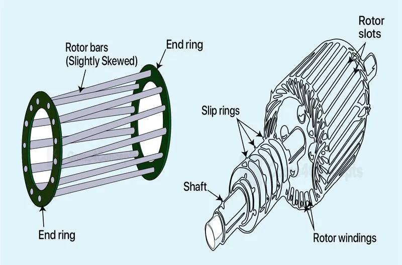
The induction machine rotor can be squirrel caged and wound rotor type. The squirrel cage is widely used for its easy to use and maintainance property, though wound rotor has an advantage of higher starting torque. The squirrel cage rotor is a cage shaped, stacked steel lamination, that are short circuited at the end by the end rings.
The diagram below shows squirrel cage and wound rotor seperately. Here the first diagram is of squirrel cage and the second diagram is of wound rotor.
Working of Induction motor
When 3 phase supply is given to the stator of an induction machine, a rotating magnetic field is created in the air gap, which cuts the rotor winding and induces emf and current at a slip frequency. Because of lentz law (electromagnetic law of induction), the motor opposes the cause of production of emf ie. the rotating magnetic field. So it starts rotating in the direction of magnetic field.
Here the frequency of rotor is S times frequency of supply.
The EMF induced in the rotor is S times the standstill EMF of rotor.
S is the slip of motor.
S= (speed of stator field - speed of rotor)/speed of stator field
Here the rotor always runs with speed less than the speed of stator magnetic field. If the rotor runs with the speed of stator magnetic field. No emf is induced or no current flows through the rotor winding and the motors stops running. The induction motor does not require an inverter to start unlike brushless dc motor.
COMPARISON.
| BRUSHLESS DC MOTOR | INDUCTION MOTOR |
| Here permanent magnets are used as field | No permanents magnets are used as fields. 3 phase supply is used |
| The field winding is on the rotor | The 3 phase field winding is placed on the stator. |
| speed of rotor does not depends upon the slip of the machine | The speed and emf induced in rotor depends on the slip value. |
| A wide range of speed regulation is achieved. | Not a very wide range of speed regulation is achieved. |
| Requires an fully controlled inverter to connect it with the utility supply | Does not require an inverter to connect it with utility supply. |
| The rotor construction and maintainance is comparitively not that easy. | The rotor construction and maintainance is easier. |
| The rotor cicuit consists of permanent magnets | The rotor consists of steel cages shorted at the ends. |
| They are not widely used in utility sector, like emergency dc motors. | They are widely used in utility sector, where a constant speed and torque is required. |
| when connected with inverters, they can have higher speed and torque. | They have comparitively lower speed, starting and running torque. |
| The working flux can not be modulated because of permanent magnets | The working flux can be modulated by varying the firing angles of the inverters used. |
| Less heat is generated in rotor with dc brushless drive | Comparitively more heat is generated because of the current flowing in rotor. |
| The peak efficiency is more than Induction motors | Average efficiency is better. |
| Permanent magnets are expensive | The cage rotors are cost efficient |
| The control is comparitively easy. |
The control laws are more complex and difficult |
SUMMARY
The author believes due to its own sets of merits and disadvantages, the DC brushless drives will likely continue to dominate in the hybrid and coming plug-in hybrid markets, and that induction drives will likely maintain dominance for the high-performance pure electrics