Project
Project:
The All-Terrain Vehicles or ATV are as the name says, the off-road terrain vehicles. They cover a wide range of terrains like mountains, rivers, forests etc. In practical they are used for rescuing operation in terrains, exploration, adventure sports etc.
This technical report aims at the analysis of model properties and the result of a BAJA ATV model using control variable transmission. We have made use of SIMSCAPE and SIMSCAPE DRIVELINE in the model.
INPUTS.
The brake and throttle are the input to the model. The throttle input signal is provided via Simulink -PS converter to the engine and the brake input signal goes to the double shoe brake block in the vehicle body. Also the CVT ratio is provided as input to the CVT.
OUTPUTS
Vehicle velocity, primary pulley and secondary pulley speeds of CVT and the distance covered by vehicle are the output of the model.
COMPONENTS
Vehicle Body, suspension, tyres, CVT, engine are the basic components of Baja ATV.
MODEL
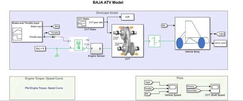
1. GENERIC ENGINES
The generic engine block represents the spark-ignition and diesel engines. The input to this block is throttle, which throttles the amount of power delivered by the engine. The rotational output of the engine is given to the engine sensor, which senses the rpm of the shaft. The shaft is then connected to the primary pulley of CVT.
2. CONTINOUS VARIABLE TRANSMITTER (CVT)
CVT is a transmission method that provides variable yet in a fixed range of gear ratio. The main purpose here is to adjust the gear ratio as per the speed of vehicle.
Two pulleys primary and secondary are connected through belt. Through variators, the pulley plates can be dragged apart as well as brought close to each other, hence changing the effective diameter of the pulley. Due to the shape of pulley, when plates are dragged away, effective diameter reduces and rotational speed of that pulley increases, thus increasing the gear ratio. Similarly, when the plates are brought closer, the effective diameter increases and rotational speed of the pulley decreases, thus decreasing the gear ratio. The variator is pushed inwards and outwards through hydraulic system. The system is such when the primary pulley moves inwards, the secondary pulley moves outwards, hence driving overspeed or the speed of secondary pulley is more than the primary pulley. When the primary pulley moves outwards, the secondary pulley moves inwards, reducing the speed of secondary pulley and the speed of secondary pulley is lesser than the primary pulley. Due to the varying gear ratio at every input, it is named as continuous variable transmitter. The CVT also facilitates reverse gear option through planetary gears attached to the shaft of secondary pulley.
The CVT model contains a variable gear, an input shaft inertia, output shaft inertia and motion sensors for the primary and secondary pulley speeds. The output of CVT is connected to a simple gear, based on vehicle requirement. The output of simple gear is connected to the vehicle body.
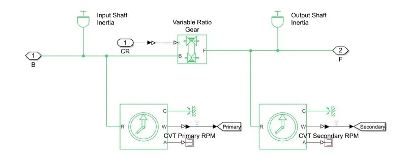
The CVT subsystem
3. VEHICLE BODY
This subsystem contains many blocks like wheels, double shoe brake and vehicle body. The vehicle body block takes care about the physical modelling parameters like mass of vehicle, aerodynamic drag, road incline, distribution of weight between axles because of the road profile, wind velocity etc. The brake signal is given to the double shoe brake block. The velocity of the vehicle is scoped.
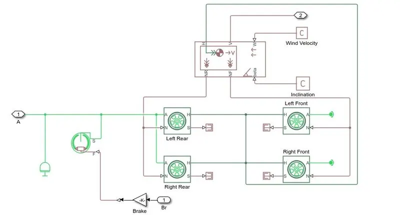
The vehicle body subsystem
OUTPUT RESULT
It is observed that the characteristics of the velocity of the vehicle is similar to the speed of secondary pulley. We can see for a constant throttle; the vehicle velocity initially increases and becomes constant. Also, when the throttle changes, vehicle velocity also changes. It is also noticed that when CVT ratio is greater than 1, secondary pulley speed is lesser than primary pulley speed. But as the CVT ratio goes below 1, the secondary pulley speed becomes more than the primary pulley speed. Well, all this time, the brake input applied is kept 0.
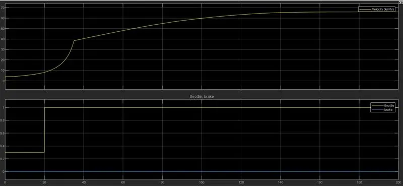
The vehicle velocity, brake and throttle plot
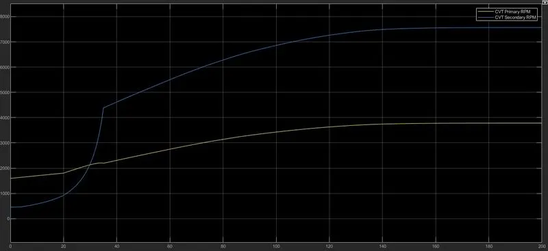
The primary and secondary pulley plot
MODIFICATION
Here in this model, the CVT ratio is provided and the vehicle velocity depends on that. But practically the CVT ratio depends on the vehicle velocity, thus forming a closed loop system. LOOKUP TABLE is used for that purpose. The output velocity becomes input to the lookup table which fetches the appropriate CVT ratio, to the CVT.
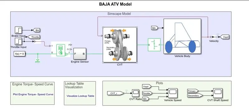
Modified ATV model
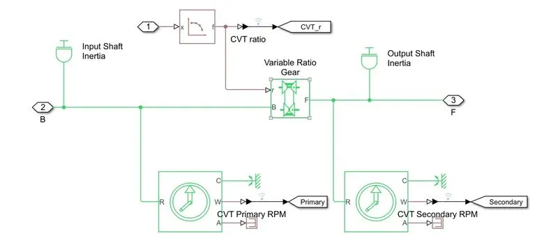
Modified CVT subsystem