Week-6 Challenge: EV Drivetrain
1. Which types of power converter circuits are employed in electric and hybrid electric vehicle?
Ans- In electric engineering, a DC to DC converter is a category of power converters and it is an electric circuit which converts a source of direct current (DC) from one voltage level to another, by storing the input energy temporarily and then releasing that energy to the output at a different voltage. The storage may be in either magnetic field storage components (inductors, transformers) or electric field storage components (capacitors).
DC/DC converters can be designed to transfer power in only one direction, from the input to the output. However, almost all DC/DC converter topologies can be made bi-directional. A bi-directional converter can move power in either direction, which is useful in applications requiring regenerative braking.
The amount of power flow between the input and the output can be controlled by adjusting the duty cycle (ratio of on/off time of the switch). Usually, this is done to control the output voltage, the input current, the output current, or to maintain a constant power. Transformer-based converters may provide isolation between the input and the output. The main drawbacks of switching converters include complexity, electronic noise and high cost for some topologies.
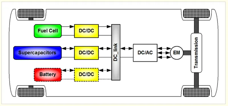
The non-isolated converters type is generally used where the voltage needs to be stepped up or down by a relatively small ratio (less than 4:1). And when there is no problem with the output and input having no dielectric isolation. There are five main types of converter in this non-isolated group, usually called the buck, boost, buck-boost, Cuk and charge-pump converters. The buck converter is used for voltage step-down, while the boost converter is used for voltage step-up. The buck-boost and Cuk converters can be used for either step-down or step-up. The charge-pump converter is used for either voltage step-up or voltage inversion, but only in relatively low power applications.
In isolated type of converters a high frequency transformer is used. In the applications where the output needs to be completely isolated from the input, an isolated converter is necessary. There are many types of converters in this group such as Half-Bridge, Full-Bridge, Fly-back, Forward and Push-Pull DC/DC converters
Each converter topology has its advantages and its drawbacks. For example, The DC/DC boost converter does not meet the criteria of electrical isolation. Moreover, the large variance in magnitude between the input and output imposes severe stresses on the switch and this topology suffers from high current and voltage ripples and also big volume and weight. A basic interleaved multichannel DC/DC converter topology permits to reduce the input and output current and voltage ripples, to reduce the volume and weight of the inductors and to increase the efficiency. These structures, however, can not work efficiently when a high voltage step-up ratio is required since the duty cycle is limited by circuit impedance leading to a maximum step-up ratio of approximately 4. Hence, two series connected step-up converters would be required to achieve the specific voltage gain of the application specification. A full-bridge DC/DC converter is the most frequently implemented circuit configuration for fuel-cell power conditioning when electrical isolation is required. The full bridge DC/DC converter is suitable for high-power transmission because switch voltage and current are not high. It has small input and output current and voltage ripples. The full-bridge topology is a favorite for zero voltage switching (ZVS) pulse width modulation (PWM) techniques.
2.An Electric Vehicle's powertrain with 72V battery pack in shown in the diagram below. The duty ratio for acceleration operation is 'd1' and for the braking operation the duty ratio is 'd2'.What is EV steady state speed if duty cycle is 70%?
Ans-We have the given parameters below,
Rated armature voltage=72V
Rated armature current=400A
Ra= 0.5Ω, KΦ= 0.7 Volt second
Chopper Switching frequency= 400 H
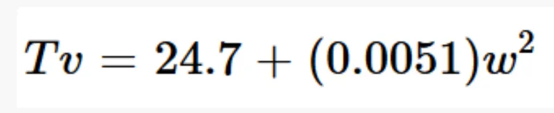
The vehicle speed-torque characteristics are given by the below equation
If duty cycle=70%
Then Vo=72*70/100
=50.4V
Tv=(Vo *KØ/Ra)-(w*KØ2/Ra)
Tv=(50.4*0.7/0.5)-(w*.72/0.5)
Tv=70.56-0.98w
For finding the value of speed,equating the above equation with the given Tv equation we get,
24.7+0.0051=70.56-0.98w
0.0051+0.98w+45.86
So by solving the above mathematical equation,we get the solution as,
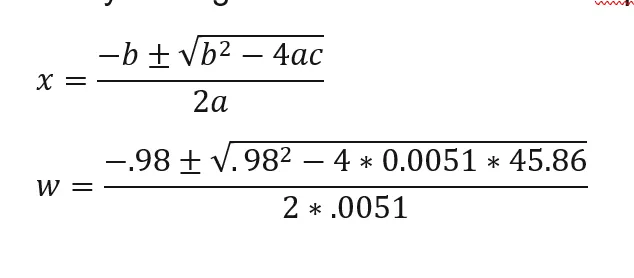
w=38.91
And -231.07
So taking the positive value of w
Speed=38.91 rad/s
3. Develop a mathematical model of a DC Motor for the below equation using Simulink.
Ans-
We have to create the mathematical model of the equation ω= V/Kϕ -Ra/Kϕϕ^2 .T,so
we have taken input voltage V=50V
T-torque
K-motor constant
Ra-Armature Resistance
we have to use different blocks for creating the model ,constant block is used give constant value.we have constant values like voltage and motor constantand and ramp block is used to output a ramp signal starting at the specified time.And for multiplication and division model is ued,to represent graphically scope is used.
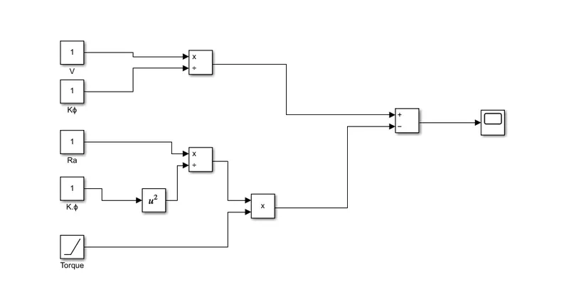
result-
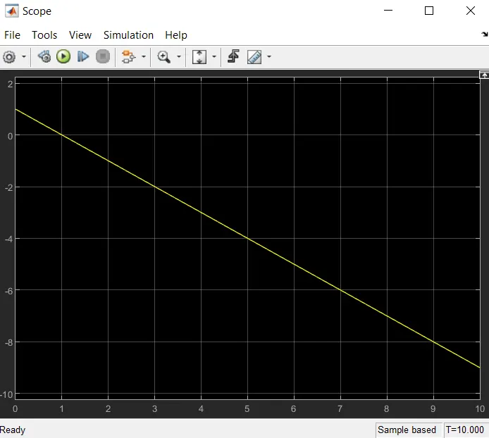
From the graph we can see that the torque and speed is inversely proportional.When the speed increases torque is decrease linearly.
4. Refer to the blog on below topic: Induction Versus DC brushless motors by Wally Rippel, TeslaExplain in brief about author’s perspective
Ans-
In the blog we can know more about the two different types of motors used in electric vehicles,and their future advancement in the automobile industry.The brushless dc and induction motor.the construction details ,working and comparisons are also given. The simplest type of motor is the brushed DC motor. In this type of motor, electrical current is passed through coils that are arranged within a fixed magnetic field. The current generates magnetic fields in the coils; this causes the coil assembly to rotate, as each coil is pushed away from the like pole and pulled toward the unlike pole of the fixed field. To maintain rotation, it is necessary to continually reverse the current—so that coil polarities will continually flip, causing the coils to continue “chasing” the unlike fixed poles. Power to the coils is supplied through fixed conductive brushes that make contact with a rotating commutator; it is the rotation of the commutator that causes the reversal of the current through the coils. The commutator and brushes are the key components distinguishing the brushed DC motor from other motor types. Brushed DC motors, featuring simple design and easy control, are widely used to open and close disk trays. In cars, they are often used for retracting, extending, and positioning electrically-powered side windows. The low cost of these motors makes them suitable for many uses. One drawback, however, is that brushes and commutators tend to wear relatively quickly as a result of their continued contact, requiring frequent replacement and periodic maintenance.
A BLDC motor with three coils on the stator will have six electrical wires (two to each coil) extending from these coils. In most implementations three of these wires will be connected internally, with the three remaining wires extending from the motor body (in contrast to the two wires extending from the brushed motor described earlier). Wiring in the BLDC motor case is more complicated than simply connecting the power cell’s positive and negative terminals; we will look more closely at how these motors work in the second session of this series. Below, we conclude by looking at the advantages of by BLDC motors. BLDC motors also offer high durability and low electric noise generation, thanks to the lack of brushes. With brushed motors, the brushes and commutator wear down as a result of continuous moving contact, and also produce sparks where contact is made. Electrical noise, in particular, is the result of the strong sparks that tend to occur at the areas where the brushes pass over the gaps in the commutator. This is why BLDC motors are often considered preferable in applications where it is important to avoid electrical noise
An induction motor (also known as an asynchronous motor) is a commonly used AC electric motor. In an induction motor, the electric current in the rotor needed to produce torque is obtained via electromagnetic induction from the rotating magnetic field of the stator winding. The rotor of an induction motor can be a squirrel cage rotor or wound type rotor. Induction motors are referred to as ‘asynchronous motors’ because they operate at a speed less than their synchronous speed Synchronous speed is the speed of rotation of the magnetic field in a rotary machine and it depends upon the frequency and number poles of the machine. An induction motor always runs at a speed less than synchronous speed because the rotating magnetic field which is produced in the stator will generate flux in the rotor which will make the rotor to rotate, but due to the lagging of flux current in the rotor with flux current in the stator, the rotor will never reach to its rotating magnetic field speed
The motor which works on the principle of electromagnetic induction is known as the induction motor. The electromagnetic induction is the phenomenon in which the electromotive force induces across the electrical conductor when it is placed in a rotating magnetic field. When the three phase supply is given to the stator, the rotating magnetic field produced on it. DC brushless drives will likely continue to dominate in the hybrid and coming plug-in hybrid markets, and that induction drives will likely maintain dominance for the high-performance pure electrics.He has explained well about their advantages and disadvanges in a very simple way,Both type have a big role in the automobile industry relevant to their different application