Week-6 Challenge: EV Drivetrain
1. Below are the 4 types of power converter circuits but the first three types are only used in EV's & HEV's.
These are:
1. AC to DC converter(Also called rectifiers): this type of converter converts the AC supply to a DC supply. Electric power is transmitted from power plants to our homes in AC form which is at a voltage of 220V & 50Hz.But the home appliances operate on DC supply so we need to convert the AC supply into a DC.Rectifiers are used in phone & laptop chargers & any other domestic appliance.
The AC supply is an alternating supply which alternativiely reverses the direction.After rectification the current is unidirectional.
A rectifier circuit usually consists of a step down transformer,a diode,a capacitor & a voltage regulator.
The 220V AC supply is converted to 10-15V AC depending on the usage.Using the diode arrangements the negative half cycle of the voltage is removed(in case of half wave rectifier) or converter to positive wave(in case of full wave rectifier).The rectified output voltage wave is smoothened using a filter capacitor & finally the voltage regulate will regulate the output voltage for our final use.
For charging the EV battery which operated at DC voltage the AC supply from the mains has to be converted to DC so the EV battery charger is equipped with this rectifier circuitry.
2. DC to AC converter(Also called Inverters):
A power inverter, or inverter, is a power electronic device or circuitry that changes direct current (DC) to alternating current (AC).[1] The resulting AC frequency obtained depends on the particular device employed. Inverters do the opposite of “converters” which were originally large electromechanical devices converting AC to DC.[2]
The input voltage, output voltage and frequency, and overall power handling depend on the design of the specific device or circuitry. The inverter does not produce any power; the power is provided by the DC source.
A power inverter can be entirely electronic or may be a combination of mechanical effects (such as a rotary apparatus) and electronic circuitry. Static inverters do not use moving parts in the conversion process.
Power inverters are primarily used in electrical power applications where high currents and voltages are present; circuits that perform the same function for electronic signals, which usually have very low currents and voltages, are called oscillators. Circuits that perform the opposite function, converting AC to DC, are called rectifiers.
In case of EV's/HEV's the battery DC voltage is given to the inverter.The inverter with the electronic switches converts the DC waveform into an alternating waveform, this alternating waveform is then given to primary of step-up/step-down transformer & the output stepped up/stepped down voltage is given to AC motor.
3. DC-to-DC converter(Also called chopper): is an electronic circuit or electromechanical device that converts a source of direct current (DC) from one voltage level to another. It is a type of electric power converter. Power levels range from very low (small batteries) to very high (high-voltage power transmission).
A DC to DC converter may be used in vehicle to step-up or step-down the DC voltage to operate different auxllaries in vehicle like infotainment, Radio, air conditioner etc.
Practical electronic converters use switching techniques. Switched-mode DC-to-DC converters convert one DC voltage level to another, which may be higher or lower, by storing the input energy temporarily and then releasing that energy to the output at a different voltage. The storage may be in either magnetic field storage components (inductors, transformers) or electric field storage components (capacitors). This conversion method can increase or decrease voltage. Switching conversion is often more power-efficient (typical efficiency is 75% to 98%) than linear voltage regulation, which dissipates unwanted power as heat. Fast semiconductor device rise and fall times are required for efficiency; however, these fast transitions combine with layout parasitic effects to make circuit design challenging.[5] The higher efficiency of a switched-mode converter reduces the heatsinking needed, and increases battery endurance of portable equipment. Efficiency has improved since the late 1980s due to the use of power FETs, which are able to switch more efficiently with lower switching losses at higher frequencies than power bipolar transistors, and use less complex drive circuitry. Another important improvement in DC-DC converters is replacing the flywheel diode by synchronous rectification[6] using a power FET, whose "on resistance" is much lower, reducing switching losses. Before the wide availability of power semiconductors, low-power DC-to-DC synchronous converters consisted of an electro-mechanical vibrator followed by a voltage step-up transformer feeding a vacuum tube or semiconductor rectifier, or synchronous rectifier contacts on the vibrator.
Most DC-to-DC converters are designed to move power in only one direction, from dedicated input to output. However, all switching regulator topologies can be made bidirectional and able to move power in either direction by replacing all diodes with independently controlled active rectification. A bidirectional converter is useful, for example, in applications requiring regenerative braking of vehicles, where power is supplied to the wheels while driving, but supplied by the wheels when braking.
Although they require few components, switching converters are electronically complex. Like all high-frequency circuits, their components must be carefully specified and physically arranged to achieve stable operation and to keep switching noise (EMI / RFI) at acceptable levels.[7] Their cost is higher than linear regulators in voltage-dropping applications, but their cost has been decreasing with advances in chip design.
DC-to-DC converters are available as integrated circuits (ICs) requiring few additional components. Converters are also available as complete hybrid circuit modules, ready for use within an electronic assembly.
Linear regulators which are used to output a stable DC independent of input voltage and output load from a higher but less stable input by dissipating excess volt-amperes as heat, could be described literally as DC-to-DC converters, but this is not usual usage. (The same could be said of a simple voltage dropper resistor, whether or not stabilised by a following voltage regulator or Zener diode.)
2 Different types of DC-DC converters are:
i. Isolated type:
1. Flyback converter: similar to buck-boost converter except it uses transformer instead of inductor to store energy.
2. Forward converter: This type uses a transformer to send energy from input to output in a single step
ii.non isolated type:
1. Buck converter: steps down the voltage
2. Boost converter: steps up the voltage
3. Buck-Boost converter: used mainly to reverse polarity but performs both step-up & step-down operation.
4. Cuk converter: it is similar to buck-boost type.
5. Charge pump: A charge pump is a kind of DC-to-DC converter that uses capacitors for energetic charge storage to raise or lower voltage. Charge-pump circuits are capable of high efficiencies, sometimes as high as 90–95%, while being electrically simple circuits.
4. AC-AC converter: A solid-state AC-to-AC converter converts an AC waveform to another AC waveform, where the output voltage and frequency can be set varied.
AC-AC converters are of following types:
- Indirect AC-AC (or AC/DC-AC) converters (i.e., with rectifier, DC link and inverter),[2] such as those used in variable frequency drives
- Cycloconverters
- Hybrid matrix converters
- Matrix converters (MC)
- AC voltage controllers
These type of conveters are not used in EV's/HEV's as the there is no AC supply in the vehicle.
2. The EV steady state speed for duty cycle of chopper = 70% is calculated as below:
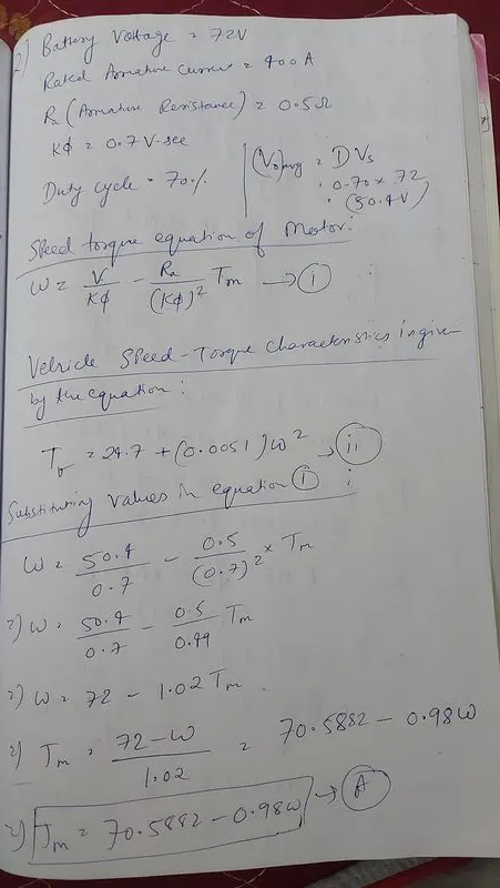
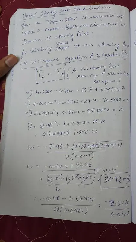
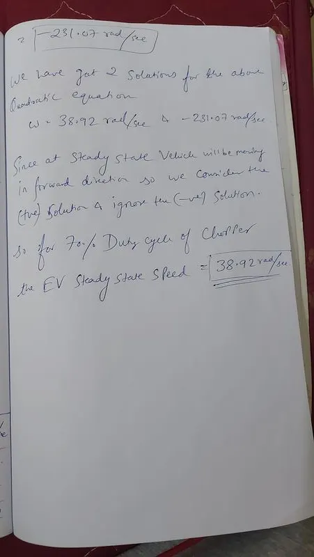
For a duty cycle of 70% for the chopper the steady seed of the vehicle & motor is 38.92 rad/sec.
3.
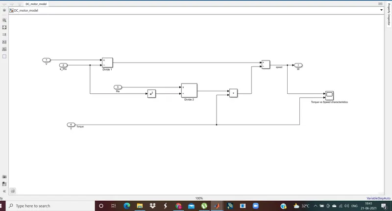
The torque equation mentioned in the challenge is converted into a mathematical model above with V(battery voltage),Ra(armature resistance),k_Phi(motor constant) & T(motor torque) as input to the model.
Battery voltage(V),Motor torque(T) are variable & k_Phi,Ra are constant.Based on these values the motor speed(w in rad/sec) is calculated from the above equation.
Torque vs Speed characteristics is plotted using scope.
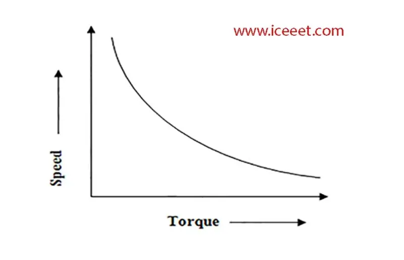
On running the simulation for above model we will get speed vs torque characteristics as shown above.
4. The author's perspective on Brushless DC motors vs Induction motors is:
There is no best motor choice in the EV or HEV powertrain as both of them will suit the customer as per their requirement & their financial budget. Both of these machines have their own pros & cons.The similar is the case with conventional IC engine vehicles(No engine can be said the best,each one of them have their own pros & cons).
Both Brushless DC motor & Induction motor drives are controlled by similar modulating inverters.The stator construction of both machines is very similar but the only difference is the rotor construction.The rotor of PMBLDC motor has permanent magnets mounted on it but for Induction motor there are windings & Conduction bars that induce magnetic fields & act as controlled magnets.
Brushless DC motors:
Pros:
1. The torque control is more effective with simple control. It provides high starting torque.
2.The control techniques for motor control is simple & less expensive.
3. The heating of rotor is less so peak efficiency is more & rotor cooling is not a issue here.
Cons:
1. The magnetic field of the permanent magnets cannot be adjusted to reduce the magnetic losses.
2.The magnetic & conduction losses are more due to permanent magnets in the rotor.
3. The overall efficiency is less due to non-adjustable magnetic & conduction losses.
4. Since it involves permanent magnets in the motor. It experiences huge forces if there is any ferromagnetic substance in its vicinity.
5. The price of Permanent magnets is more . Around $50 per kg.
Induction Motors:
Pros:
1. Magnetic & conduction losses can be adjusted optimized depending on speed as there is no permanent magnets involved.
2. The overall efficiency of these motors is more compared to PMBLDC due to less magnetic & conduction losses.
3. The magnetic losses can be controlled thus optimizing the losses & efficiency.
4. The rotating rotor in case of Induction produces no or negligible voltages so protection needed for them is less.
5. The cost permanent magnets is eliminated here.
Cons:
1. The heating of rotor is more & rotor cooling should be taken care of.
2. The effective Torque control for these motors is less with simple control.The torque characteristics for these motors can be equalled to that of DC motors by using feedback controls.
3. The motor control techniques are complex & expensive for these machines.
4. The overall heating of the these motor is more and I^2*R losses are more due to involvement of more conductors & windings so a very good cooling system has to provided to avoid overheating & damage to the motors.
Conclusion:
1. PMBLDC motor powertrains are generally deployed in HEV's due to its relatively low cost & simple control & where medium performance is expected from electric powertrain.
2. Induction motor drives are mostly used in High performance pure EV powertrains where the initial investment is high but the future investments are insignificant.
3. In the coming years both of these machines will have their own importance & will find their usage in EV's & HEV's.
4. In 1990's where most EV's & Hybrids mostly involved BLDC motors(except GM's EV1 which had induction machine drive), in 2000's its induction machines which is more common.