Week-6 Challenge: EV Drivetrain
- Aim:
- To get to know the types of converters used in HEV and EV vehicles.
- To find the speed using torque-speed relation.
- To get to know about induction and DC brushless motors.
- Objectives:
- To get information on converters for HEV and EV vehicles.
- Find the speed using torque-speed expression.
- Try to find the best options for motors for HEV or EV vehicles.
- Method :
1. Which types of power converter circuits are employed in an electric and hybrid electric vehicle?
- A motor drive consists of a power converter and the controller. The power electronic converter handles the flow of bulk power from the source to the motor input terminals. The controller process the command input and the feedback information to generate the switching signals for power converter semiconductor switches.
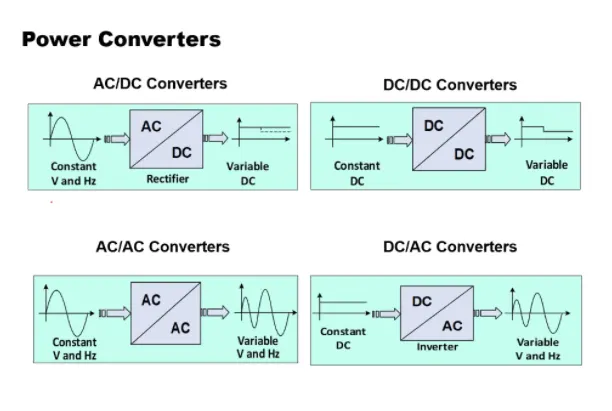
- The power converter can be a DC drive supplying a CD motor or an AC drive supplying an AC motor.
- A DC/DC converter in its basic form converts unregulated DC input voltage at a certain level to regulated DC output voltage at a different level with very high conversion efficiency. These are operated at very high frequency. The switches are turned ON and OFF by pulse width modulation(PWM).
- The power converter is made of high power fast-acting semiconductors devices, such as a bipolar junction transistor. There are some other transistors such as MOSFET, IGBT, SCR, GTO, MCT. These devices are used as on-off electronics switch to convert the fixed supply voltage into a variable voltage and variable frequency supply.
- All these devices have a control input gate or base through which the devices are turned on and off as per the command generated by the controller.
- There are two types of step converters. When a low voltage input is converted into a high voltage output it is a step-up converter. Whereas when a high voltage input is converted into a low voltage output it is a step down converter.
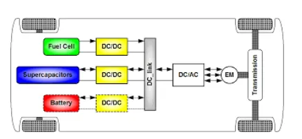
DC-DC converter for electric vehicle
2. An Electric Vehicle's powertrain with 72V battery pack in shown in the diagram below. The duty ratio for acceleration operation is 'd1' and for the braking operation the duty ratio is 'd2'.
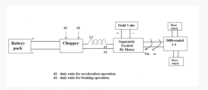
Motor and Controller Parameter
Rated Armature Voltage = 72V
Rated Armature Current = 400A
Ra = 0.5 Ω">ΩΩ
K∅">K∅= 0.7 Volt second
Chopper Switching Frequency = 400Hz
The vehicle characteristics are given by the equation
Tv=24.7-0.0051ω2">Tv=24.7−0.0051ω2
What is EV steady state speed if the duty cycle is 70 % ?
As given ,
Battery pack in EV Drivetrain = 72 v(armature voltage)
Armature current = 400 A
Armature Resistance Ra = 0.5 Ω
Motor constant = 0.7 V-s
Chopper Switching frequency = 400 Hz
For the value of “V” i.e Average Voltage we need multiply the Armature Voltage with Duty Cycle,
Speed-Torque Equation of Motor,
`ω=V/K−Ra/K2×Tm`
Where,
Tm">TmTm= Torque
V = Voltage
N (ω) = Motor Speed
Ra = Armature Resistance
K = Motor Constant (Armature control motor)
The Derived formula for motor speed characteristics is,
`Tm=V/Ra.K−K2/Ra×ω…………………..(1)`
After substituting the input value in eq (1)we get
`Tm=50.4×0.7/0.5-(0.7)^2/0.5×ω`
`Tm=70.56-0.98ω2 …………………….(2)`
We have been given that vehicle speed torque characteristics as,
`Tv=24.7-0.0051ω2 …………………..(3)`
At Steady state ,
`Tv=Tm …………………..(4)`
Substituting Eq no. 2 and Eq no. 3 in Eq no. 4 we get,
`Tv=Tm`
`24.7-0.0051ω2=70.56-0.98ω2`
`0.0051ω2+0.98ω-45.85=0`
We now use the QUADRATIC EQUATION FORMULA to solve the above Equation,
`0.0051ω2+0.98ω-45.85=0 comparing it with (ax)^2+bx+c=0`
Where ,
a = 0.0051 b = 0.98 c = 45.85
For solving the QUADRATIC EQUATION , we have to use below formula,
`x=ω`
`x=-b±√(b2-4ac)/2a`
`x=−0.98±√((0.98)^2−4(0.0051)(−45.85))/2.(0.0051)`
ω = 38.92 rad/sec
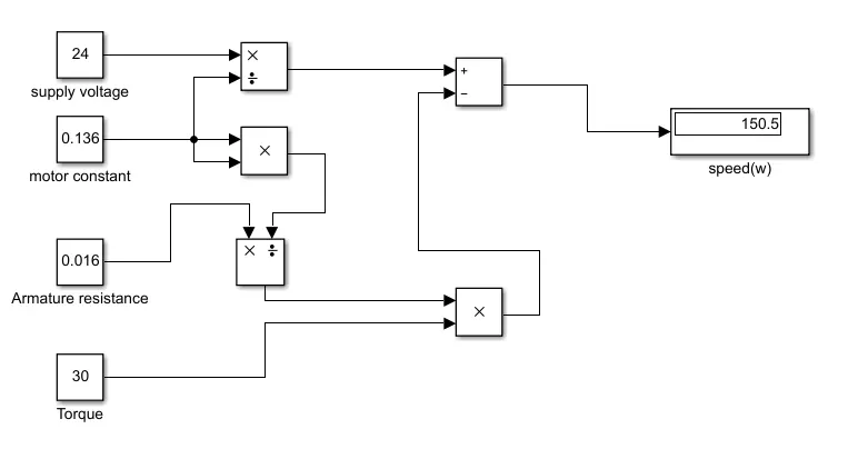
3.Develop a mathematical model of a DC Motor for the below equation using Simulink.
ω= V/Kϕ -Ra/(Kϕ)^2 .T
4. Explain in brief about the author’s perspective.
solution: The author states that every engine is unique in its own ways. There is no one best performing engine. It all depends on the requirements of the user. Given below are the differences between Ac induction and BLDC motors.
|
AC INDUCTION |
BRUSHLESS DC |
|
1.An AC induction motor does not have any magnets on the rotor; instead, it has a series of laminations and winding. When 3-phase power is applied to the stator of the motor, a rotating magnetic field is generated. This rotating magnetic field creates a current flow in the rotor via induction. The rotor current creates its own magnet that interacts with the stator field and generates torque. |
1.Alternatively, a BLDC motor replaces the windings on the rotor with a series of permanent magnets. These magnets create a magnetic field that interacts with the stator’s field and generate torque |
|
2.Most AC induction motors can be run directly off of AC power with no controller, but if variable speed is required—as is the case in many pump applications—this advantage is eliminated since a VFD must be installed between the AC power and the motor |
2.a BLDC motor requires the stator’s magnetic field to be precisely controlled and aligned with the rotor position and its fixed magnets. The stator field is controlled by a device that is all but identical to a VFD used with an AC induction motor but with one additional input; a shaft encoder attached to the rotor is required to help the motor controller keep the rotor and stator fields in proper alignment. |
|
3. Lower efficiency |
3. higher efficiency |
|
4. Torque control not as precise as BLDC |
4. Precise control of torque |
|
5. Response time is a little less. |
5.a BLDC motor’s inherently fast response allows the mechanical connection to be significantly simplified. |
|
6. Invertor is not needed |
6. Inverter is needed |
|
7. Cannot operate at unity power factor |
7. They can operate at a unity power factor |
|
8. More heat is generated |
8. Less heat is generated |
He also concluded that
For an HEV or plug-in hybrid, BLDC is preferred and for a pure electric vehicle, an AC motor is preferred.
CONCLUSION:
- We have discussed about the different types of power converter circuit employed in electric and hybrid electric vehicles.
- The EV steady state Speed of an EV Drivetrain was determined with the given inputs conditions.
- We have done simulation for the given formula.
- We have studied a Blog on the Topic “Induction motor Vs DC Brushless motor by
Wally Rippel” , “Nikola Tesla” and explained about the author’s perspective.-
REFERENCE:
2.https://www.electronicshub.org/12v-dc-220v-ac-converter-circuit/
3.https://www.electrical4u.com/chopper-dc-to-dc-converter/
4.https://www.elprocus.com/what-is-a-flyback-converter-design-its-working/
5.https://circuitdigest.com/electronic-circuits/flyback-converter-circuit-diagram
8.https://matlabhelper.com/blog/simulink/electric-vehicle-simulation-in-simulink/