Week-6 Challenge: EV Drivetrain
Aim:-
- To Understand different power converters in EV and HEV
- Duty ratio and Power electronics on electric vehicle
- Author’s perspective of Induction Versus DC brushless motors by Wally Rippel, Tesla
Study 1:- To Understand different power converters in EV and HEV
Power Converters:-
There are 4 different types of power electronic converters used for performing different functions. They are shown below
- AC to DC (Rectifier)
- DC to DC (Chopper)
- DC to AC (Inverter)
- AC to AC (Cycloconverters)
AC to DC Converter:-
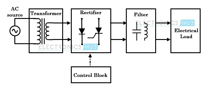
An AC to DC converter is also called a rectifier, which converts an AC voltage to DC voltage. The block diagram of an AC to DC converter is shown in figure below.
The Essential components that are present in the AC to DC Converter block diagram are
- Transformer
- Rectifier
- Filter
- Electrical Load
- Control back
DC to DC (Chopper):-
An DC to DC converter is also called a Chopper,which converts a fixed input DC voltage to variable DC output voltage. The block diagram of an DC to DC converter is shown in figure below.
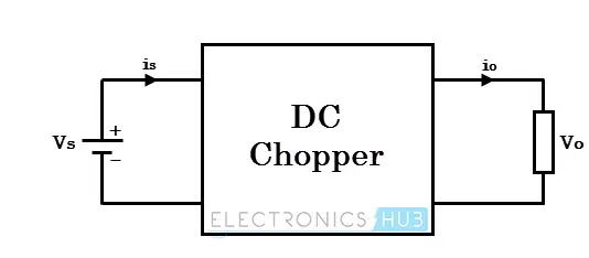
DC choppers are mainly used in DC drives, i.e., electric vehicles and hybrid electric vehicles.
DC choppers are classified into two basic types based on input and output voltage levels and are shown below
- Step down Chopper
- Step up Chopper
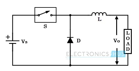
Step down Chopper:-
A step-down chopper produces an average output voltage lower than the input DC voltage. The circuit for this converter is shown in figure below.
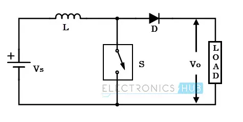
Step up Chopper:-
A step-up chopper produces an average output voltage greater than the input DC voltage. The circuit for this converter is shown in figure below.
DC to AC Converter:-
An DC to AC converter is also called an Inverter,which converts fixed DC supply voltage to variable AC voltage. The block diagram of an DC to AC converter is shown in figure below.
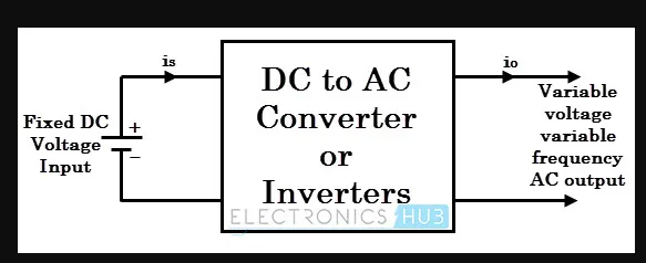
Here the fixed DC voltage is obtained from batteries or by DC link in most power electronic converters. The output of the inverter can be variable/ fixed AC voltage with variable/fixed frequency.These can be single phase or three phase inverters depending on the supply voltage. These converters are mainly divided into two groups. One is PWM based inverters and other multilevel inverters.
AC to AC Converters:-
An AC to AC converter is also called a Cycloconverter,which converts AC power of certain frequency to AC power of another frequency . The block diagram of an AC to AC converter is shown in figure below.
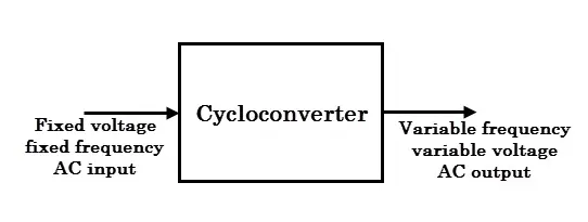
They are 2 main types of AC to AC Converters. They are
- Cyclo Converters
- Matrix Converters
Study 2:- An Electric Vehicle's powertrain with 72V battery pack in shown in the diagram below. The duty ratio for acceleration operation is 'd1' and for the braking operation the duty ratio is 'd2'.The other parameters of the electric vehicle is given below,
Motor and Controller Parameters:
Rated Armature voltage= 72 V
Rated armature current= 400 A
Ra= 0.5Ω,KΦ= 0.7 Volt second
Chopper Switching frequency= 400 Hz
vehicle speed-torque characteristics are gien as
`T tr= 24.7+0.0051w^2`
What is EV steady state speed if duty cycle is 70%?
Solution:-
From DC machine Torque speed Relation:-
`T = frac{V.km(phi)}{Ra}-frac{km(phi)}{Ra}.w`
where
T - Motor Torque
V - Voltage supply
Ra - Armature resistance
`km(phi)` - Motor Constant
w - Angular speed of motor
Voltage (Motor) = Voltage of Armature * duty cycle
= 72*0.7
= 50.4 volts
`Tm = frac{50.4 . 0.7}{0.5}-frac{w.(0.7)^2}{0.5}` ----------eq 1
Given T- vehicle
`Ttr = 24.7+0.0051w^2` -------eq 2
Now from eq 1 & eq 2
frac{50.4 . 0.7}{0.5}-frac{w.(0.7)^2}{0.5} = 24.7+0.0051w^2
from above equaion we get the the quadraic equation
`0.0051w^2+0.98w-45.8=0`
Now solving the Quadraic equation by using the formula
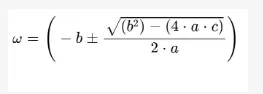
Now adding the valves
where
a = 0.0051
b = 0.98
c = 45.8
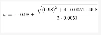
`w =frac{ -0.98+-1.377}{0.0102}`
so we will have 2 solutions for 'w'
Therefore The angular speed is
`w = 38.92 frac {rad}{sec}` or `w = -231.08 frac {rad}{sec}`
Hence we take the angular speed value as w = 38.92 frac {rad}{sec}`
Study 3:-
Refer to the blog on below topic:
Induction Versus DC brushless motors by Wally Rippel, Tesla
Explain in brief about author’s perspective.
- The author explains about the Dc brushless motor and induction motor has difference similar to the IC engine Configurations Such as V-twin,inline,radial are used in different applications.
- Uses Rotor permanent magnets that generate a DC magnetic field
- stator core interacts with currents flowing within the windings to produce a torque interaction between the rotor and stator.
- Requires angle position sensor for operating
- Dc brushless motors achieve high peak point efficiency,heat generated is less and cooling is easy.
- Induction motor is suited for high performance applications because as size losses are not increased,it is low cost as it does not provide permannent magents
- speed is controlled by PWM method in DC brushless motor.
- speed is controlled by alternating RMS speed by alternating frequency fed in voltage.
- The 3-phase induction motor and the DC brushless motor are virtually identical.
- Induction machines are more difficult to control.