EV Drivetrain
Target:-
- To study in brief about power electronic devices.
- To solve a power electronic problem.
Objective:-
- Which types of power converter circuits are employed in an electric and hybrid electric vehicle?
-
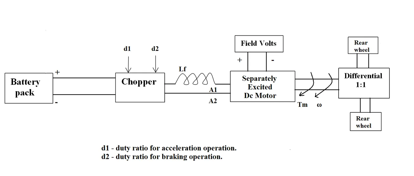
An Electric Vehicle's powertrain with 72V battery pack in shown in the diagram below. The duty ratio for acceleration operation is 'd1' and for the braking operation the duty ratio is 'd2'.
The other parameters of the electric vehicle are given below,
Motor and Controller Parameters:
Rated Armature voltage= 72 V
Rated armature current= 400 A
Ra= 0.5Ω, KΦ= 0.7 Volt second
Chopper Switching frequency= 400 Hz
The vehicle speed-torque characteristics are given by the below equation

What is EV steady-state speed if the duty cycle is 70%?
- Refer to the topic-Induction Versus DC brushless motors by Wally Rippel, Tesla and Explain in brief the author's perspective?
Theory:-
-
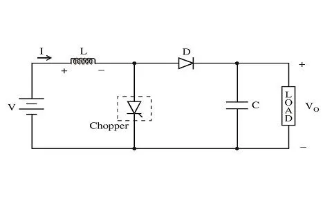
Types Description Diagram 1) DC-DC Converter Chopper- A DC-DC Converter is also known as Chopper. A Chopper is a power electronic device which can convert any DC voltage into higher od the lower voltage keeping the power in constant a chopper uses thyristor, diode, inductor, a capacitor in combination od these things they form a chopper generally there are 3 types of a chopper-
i- Buck Converter (StepUp)
ii- Boost Converter (StepDown)
iii- Buck-Boost Converter
These Converters are basically used in DC Drive circuit but in EVs and HEVs they help in controlling circuit and the power Relays and powering the digital display which requires different types of Voltage.
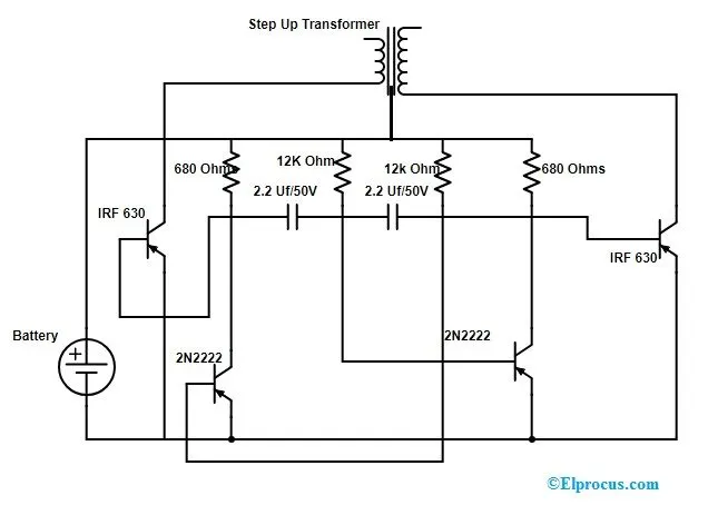
2) DC-AC Converter Inverter- A DC-AC converter is also known as Inverter an inverter is a power electronics device which can converter a steady step signal (dc) into a sinusoidal signal (ac) waveform including the Amplitude and frequency but in this case, the power is reduced this is done by the help of transformer, thyristor, MOSFET this are classified according to the output-
i- Square Wave Inverter
ii- Sine Wave Inviter
iii- Modified Sinewave Inverter
This convert is basically used in home appliances, factories but in EVs and HEVs they are majority used for 3phase Induction Motors for the powering the wheels and controlling the gears.
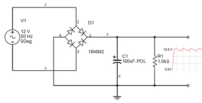
3) AC-DC Converter Rectifier- A AC-DC converter is also known as Rectifier A Rectifier is a power electronics converter which can be used to convert a transformer, diode, thirster or the MOSFET, inductor and the capacitor this reduces the power input as a compound to output power due to so many losses in the circuit as it is a long circuit with a more voltage dropping elements. There are 3 types of rectifiers which can be used in 1phase, 3 phase, 6 phase, etc-
i- Bridge Rectifier
ii-Full Wave Rectifier
iii- Half Wave Rectifier
The use of rectifier is very often used in a regular lifestyle like chargers. In EVs and HEVs they are used in charging as those vehicles required a large amount of power storing devices so, they are used in superchargers for fast charging and also in the home charges and on regenerative braking.
4) AC-AC Converter Cyclonoconvter- A AC-AC converter is also known as Cyclonoconvter. A cyclnoconvter is a power electronic device which is used for converting any frequency into another frequency of ac with the help of thyristor or MOSFET there are 3 types of the converter-
i- Blocking Mode
ii-Circulation Current
iii- 1Phase to 1 Phase Cycloconvter
The uses of this are in EVs and HEVs are to control the speed of the single-phase if an Induction Motor which helps in varying a very large amount of speed variation.
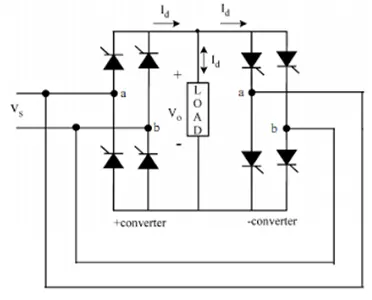
- There is no theory.
- There is no theory.
Solution:-
- There is no solution this is only for understanding the different types of the converter.
- Given:-
- `V_s = 72V`
- `I_a = 400 A`
- Ra= 0.5Ω
- `kphi =0.7`volts/sec
- `f_c = 400Hz`
- `T_D = 70% = 0.7`
- `V_(as) = 0.7 * 72 = 50.4 V`
- `omega = ?`
- `T_V = 24.7 + 0.0051omega^2` --------------------------------------------------------------------------------------- Equation (1)
- Torque Speed Charcterstics of Dc Machine is
- `T_d = (Vkphi)/R_a - (Kphi^2)/R_a * omega`
- substutie all in the given in the above equation
- or,`T_d = (50.4 * 0.7)/ 0.5 - (0.7^2)/0.5 * omega`
- or,`T_d = 70.56 - 0.98omega` ----------------------------------------------------------------------Equation (2)
- Solving the equation 1 and 2
- or,`24.7 + 0.0051omega^2 = 70.56 - 0.98omega`
- or,`0.0051omega^2 + 0.98omega - 45.86 = 0`
- Dividing thee above equation by 0.0051 on both sides
- or, `(0.0051omega^2)/0.0051 + (0.98omega)/0.98 - 45.86/0.0051 = 0`
- or, `omega^2 + 192.156omega - 8992.150 = 0`
- on solving the above quadratic equation we will get two values of `omega`
- or,`omega_1 = 39.115`rad/sec and `omega_2 = -231.0718`rad/sec
- As speed of any mother canoott be -ve so the value of `omega` should be 39.115 rad/sec
- `omega_1 = 39.115`rad/sec`
- there is no solution as this is perspective view is required from that blog.
Conclusion:-
- There is the requirement of all 4 types of converter as all are necessary for the driving of a vehicle.
- The speed of the vechile is `omega_1 = 39.115`rad/sec`
- In brushless machines, the rotor includes two or more permanent magnets that generate a DC magnetic field. During this turn, the magnetic field enters the stator core and interacts with currents flowing within the windings to produce a torque interaction between the rotor and stator. As the rotor rotates, it is necessary that the magnitude and polarity of the stator currents should be continuously varied in the right way so that the torque remains constant and the conversion of electrical to mechanical energy is efficient. So, the device that provides this current control is called an inverter. Without it, brushless motors are useless motors. A brushless DC motor produces no starting torque when directly connected to fixed frequency utility power. They really need the aid of an inverter whose “phase” is maintained in step with the angular position of the rotor. One of the main differences is that much less rotor heat is generated with the DC brushless drive. Rotor cooling is easier and peak point efficiency is generally higher for this drive. In an ideal brushless drive, the strength of the magnetic field produced by the permanent magnets would be adjustable.DC brushless drives require an absolute position sensor. The induction rotor has no magnets – just stacked steel laminations with buried peripheral conductors that form a “shorted structure.” Currents flowing in the stator windings produce a rotating magnetic field that enters the rotor. In turn, the frequency of this magnetic field as “seen” by the rotor is equal to the difference between the applied electrical frequency and the rotational “frequency” of the rotor itself. Accordingly, an induced voltage exists across the shorted structure that is proportionate to this speed difference between the rotor and electrical frequency. In response to this voltage, currents are produced within the rotor conductors that are approximately proportionate to the voltage, hence the speed difference. Finally, these currents interact with the original magnetic field to produce forces – a component of which is the desired rotor torque. The fact that induction motors are directly compatible with conventional utility power is the main reason for their success. When a 3-phase induction motor is connected to utility type 3-phase power, torque is produced at the outset. the motor has the ability to start under load. No inverter is needed. In contrast, induction machines have no magnets and B fields are adjustable. Induction drives require only a speed sensor. Both DC brushless and induction drives use motors having similar stators. Both drives use 3-phase modulating inverters. The only differences are the rotors and the inverter controls. And with digital controllers, the only control differences are with control code.