Week-6 Challenge: EV Drivetrain
1. Which types of power converter circuits are employed in an electric and hybrid electric vehicle?
There are 4 types of power converter circuits are employed in an electric and hybrid electric vehicle:
The main aim of the converter is to produce conditioning power with respect to a certain application Modern power electronic converters are involved in a very broad spectrum of applications like switched-mode power supplies, active power filters, electrical-machine-motion-control, renewable energy conversion systems distributed power generation, flexible AC transmission systems, and vehicular technology, etc.
A power electronic converter uses power electronic components such as SCRs, TRIACs, IGBTs, etc. to control and convert electric power. The main aim of the converter is to produce conditioning power with respect to a certain application.
The block diagram of a power electronic converter is shown. It consists of an electrical energy source, power electronic circuit, a control circuit and an electric load. This converter changes one form of electrical energy to another form of electrical energy.
Depending on the type of function performed, power electronic converters are categorized into the following types.
AC to DC = Rectifer: It converts AC to unipolar (DC) current
DC to AC = Inverter: It converts DC to AC of desired frequency and voltage
DC to DC = Chopper: It converts constant to variable DC or variable DC to constant DC
AC to AC = Cycloconverter, Matrix converter: It converts AC of the desired frequency and/or desired voltage magnitude from a line AC supply.
AC-DC converter
PHEVs and EVs are arranged also with an AC-DC converter which supplies electric power from a commercial power system to an onboard high-voltage battery.
The AC-DC converter is essential to work more proficiently to cut the charging time and also to be reduced so as to be fitted in a limited space. The problems lie
in large and heavy coil parts and large power loss accompanied by high-frequency switching. The AC/DC converter consists of a power factor correction (PFC)
which converts input AC voltage into DC voltage, an H-bridge circuit which converts the DC voltage into high-frequency AC voltage, a high-frequency transformer
which regulates transformation and insulation, and a circuit which recties and smooths high-frequency AC voltage. The problem with the AC/DC converter is that it
includes big power loss in high-frequency switching. While the increase of switching frequency can decrease the volume of coil parts, power loss by the power
device increases.
DC-AC converter
The DC-AC converter (inverter) comprises six bidirectional semiconductors (IGBT). The main source of electrical power is the battery which is a DC source.
The DC output of the battery is bucked or boosted according to the requirement and then converted into AC using a DC-AC inverter. The function of an inverter is to change a dc input voltage to asymmetric ac output voltage of desired magnitude and frequency. The output voltage waveforms of ideal inverters should be sinusoidal.
DC-DC converter
Usually, AC motors are used in HEVs or EVs for traction and they are fed by inverter and this inverter is fed by a DC-DC converter. The most commonly DC-DCconverters used in an HEV or an EV are:
Unidirectional Converters: They provide to several onboard loads such as sensors, controls, entertainment, utility and safety types of equipment.
Bidirectional Converters: They are used in places where battery charging and regenerative braking is required. The power ow in a bi-directional converter is usually from a low voltage end such as a battery or a supercapacitor to a high voltage side and is referred to as boost operation.
The DC-DC converter and the boost DC-DC converter with the resonant circuit is more suitable for low-power BEVs and PHEVs because of their soft switching,noise-free operation, low switching loss and high efficiency. a specific DC-DC converter to be integrated into the high voltage (HV) DC link of the powertrain.
For bidirectional electric sources like SCs and batteries, bidirectional DC-DC converters are essential to absorb the regenerative braking energy, which maximizes the overall efficiency of the system.
The DC-DC converters utilized in BEV and PHEV powertrains primarily use Si-based semiconductors which limits their efficiency to 92–93%, allows a maximum switching frequency up to 30 kHz and attains only 3–12 W/in3 power density.
Different DC-DC converter used in BEVs and PHEVs are Boost DC-DC converter (BC)Interleaved 4-Phase Boost DC-DC converter (IBC)Boost DC-DC Converter with Resonant circuit (BCRC)Full bridge Boost DC-DC converter (FBC)Isolated ZVS DC-DC converters (ZVSC)Sinusoidal Amplitude HV DC bus converter (SAHVC)Multiport isolated DC-DC converter (MPC)Multi-device Interleaved Bidirectional DC-DC converter (MDIBC).
AC-AC converter A solid-state AC-to-AC converter converts an AC waveform to another AC waveform, where the output voltage and frequency can be set randomly.
This change is mainly essential in case of speed controlling of machines, for low frequency and variable voltage magnitude applications as well. We know that there are different types of loads that work with different types of power supplies like single-phase, three-phase supply, and the supplies can be differentiated based on the voltage and frequency range also.
These types of power electronic converters are used to convert the alternating current waveforms of specific magnitude and specific frequency into alternating current waveforms with different magnitude and different frequency, as the signal remains AC, hence this converter is termed as AC to AC converter.
To operate a few devices and machines we require some specific voltage with a specific frequency which can be obtained using AC to AC converters. By regulating AC power using the AC to AC converter we can regulate the speed of induction motors. There are different types of AC to AC converters which are classified based on different criteria. The AC to AC converters can be classified into different types:1.Cycl converters2.AC to AC Converters with DC link3.Matrix Converters4.Hybrid Matrix Converters
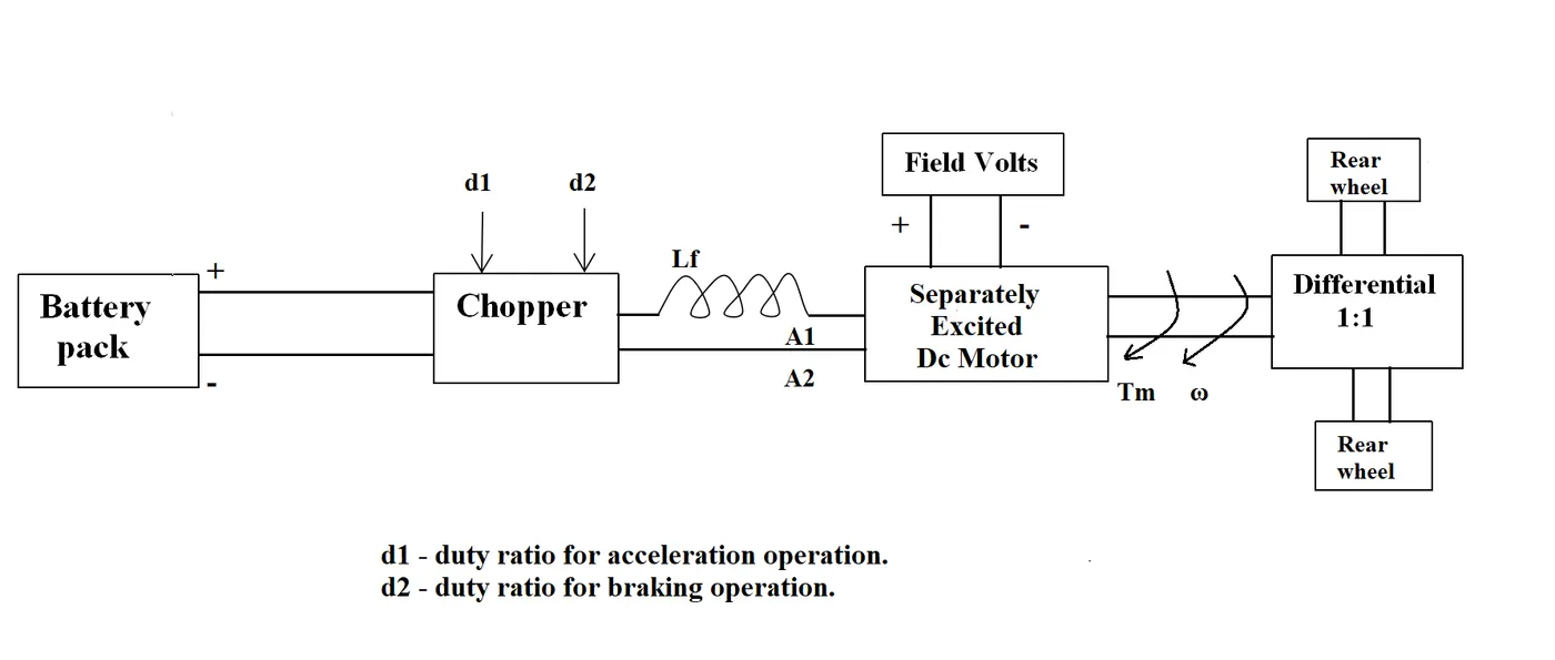
2. An Electric Vehicle's powertrain with a 72V battery pack in shown in the diagram below. The duty ratio for acceleration operation is 'd1' and for the braking operation the duty ratio is 'd2'.
The other parameters of the electric vehicle is given below,
Motor and Controller Parameters:
Rated Armature voltage= 72 V
Rated armature current= 400 A
Ra= 0.5Ω, KΦ= 0.7 Volt second
Chopper Switching frequency= 400 Hz
The vehicle speed-torque characteristics are given by the below equation

What is EV steady-state speed if the duty cycle is 70%?
Mass(m) = 1000kg
Drag coefficient cd=0.2
Frontal Area(A) = 2 sqm
coefficient of rolling resistance= 0.009
Gear ratio C1=1
Density=1.1614 kg/ cubmtr
radius of the wheel = 11 inches
Rated armature voltage= 72V
Rated armature current= 400A
Armature Resistance Ra= 0.5Ω
Armature Inductance La = 8 mH
Motor Constant Kφ = 0.7
V-sChopper Switching frequency = 400 Hz
Duty Cycle = 70%
The Rolling Resistance Force
Frr = rr.m.g
Drag Force
Fad = 0.5.ρ.A.v^2.Cd
The Total Tractive Force
Fte = Frr + Fad
Speed-Torque Equation for D.C Motor
ω = (V/kφ)-(T.R/(kφ)^2)
Solution-
Rolling resistance
Frr = rr.m.g
Frr = 0.009*1000*9.81
Frr = 88.29 N
Drag Force
Fad = 0.5.ρ.A.v^2.Cd
Fad = 0.5*1.1614*2*v^2*0.2
Fad = 0.232*v^2
Fad = 0.232*ω^2*(0.28)^2
Fad = 0.01821*ω^2
The Total Tractive Force
Fte = Frr + Fad
Fte = 88.29+(0.01821*ω^2) ----------Equation-1
Fte =G.T/r
Substituting in (1)
(1*T)/0.28 = 88.29+(0.01821*ω^2)
TTR = 24.72+0.0051*ω^2 --------- Equation-2
The vehicle characteristics are given by the equation(2) and it's derived TTR=24.7+0.0051w2 Which is given in the question
Speed-Torque Equation for D.C Motor
ω = (V/kφ)-(T.R/(kφ)^2)
By rearranging it in form torque equation
T = ((V.kφ)/R)-(ω.(kφ)^2/R)
Substituting the values of voltage, Armature Resistance, the motor constant
Before that, In the question, it is given that the duty cycle is 70%
Therefore we need the find out the voltage at 70% duty cycle
V = 72*0.7 = 50.4V
T = ((50.4*0.7)/0.5)-((ω.(0.7)^2)/0.5)
Tm = 70.56-(ω*0.98) ---------Equation (3)
At the steady-state condition of EV
TTR = Tm
Now substituting the values of TTR and Tm i.e equation (2) and (3)
24.72+0.0051*ω^2 = 70.56-(ω*0.98)
(0.0051*ω^2) + (ω*0.98)-45.84 = 0
Omega value will always be positive therefore ω = 38.90 rad/sec.
Result- EV steady state speed if duty cycle is 70% is,
ω = 38.90 rad/sec.
3) Study the blog on Induction vs. DC brushless motors by Wally Ripple, Tesla & explain in brief about the author’s perspective.
Wally Ripple is a long-time proponent of electric vehicles. Prior to joining Tesla Motors, he was an engineer at AeroVironment, where he helped to develop the Ev1 for GENERAL MOTORS.
He was featured in the documentary movie – Who Killed the Electric Car? Wally has also worked for the Jet Propulsion Laboratory on electric vehicle battery research, among other projects.
In 1968 as a Caltech undergraduate student, he built an electric car (A converted 1958 Volkswagen Microbus) and won the great Transcontinental electric car race against MIT.
He has written a blog on Induction Motor Vs. DC Brushless Motors by comparing all its strengths and weaknesses.
Geometry & Principle –
In brushless machines, the rotor has 2 or more permanent Magnets which will generate a DC magnetic field and in turn, this magnetic field enters the stator core and interacts with currents flowing within windings to produce a torque interaction between the rotor and stator.
The stators for the 3 phase induction motor & DC brushless motor are virtually identical. Both have three sets of “Distributed Windings” that are inserted within the stator core and the essential difference between the two machines is the Rotor.
As the rotor rotates, it is necessary that the magnitude and polarity of the stator currents be continuously varied and in just the right way such that the torque remains constant and the conversion of electrical and mechanical energy is optimally efficient. The device that provides the current control is called an inverter. Without it, the brushless motors are useless.
Unlike DC brushless rotors, the induction rotor has no magnets – just stacked steel laminations with buried peripheral conductors that form a ‘Shorted Structure’. Currents flowing in the stator windings produce a rotating magnetic field that enters the rotor. In turn, the frequency of this magnetic field as ‘seen’ by the rotor is equal to the difference between the applied electrical frequency and the “Rotation Frequency” of the rotor.
An induced voltage exists across the shorted structure and that is proportionate to this speed difference between the rotor and electrical frequency. In response to this voltage-current are produced within the rotor conductors that are approximately proportionate to the voltage, hence the speed difference. Finally, these currents interact with the original magnetic field to produce forces – a component of which is the desired rotor torque.
The significant difference in the geometry is the rotor and the principle of inverter control.
Brushless machine requires position sensors whereas the induction machine requires the speed sensors. Brushless / Induction –The induction machines are capable to start under load and they require an inverter.
In contrast, a brushless DC motor produces no starting torque when directly connected to fixed frequency utility power. They really need the aid of an inverter whose “phase” is maintained in step with the angular position of the rotor.
Induction machines cannot operate from DC; AC is must and shaft speed is proportionate to line frequency.IMs have limited starting torque and somewhat limited running peak torque capabilities when compared to DC type machines
Adding an inverter makes it possible to power an induction machine from a battery or other DC source; variable speed also becomes possible simply by adjusting the inverter frequency.
Torque performance of IMs is low as compared to DC machines.
Add some feedback loops to IMs such that the inverter produces the exact frequency that the motor desires and the induction motor is capable of competing with DC and DC brushless for vehicle applications.
DC brushless drives require an absolute position sensor, while induction drives require only a speed sensor and these difference are relatively small.
One of the main differences is that much less rotor heat is generated with the DC brushless drive. Rotor cooling is easier and peak point efficiency is generally higher for this drive.
The DC brushless drive also can operate at a unity power factor, whereas the best power factor for the induction drive is about 85 per cent. Therefore, the peak point energy efficiency for a DC brushless drive will typically be a few percentage points higher than for an induction drive.
The DC brushless drive can also operate at unity power factor, whereas the best power factor for the induction drive is about 85 per cent this means that the peak point energy efficiency for the DC brushless drive will typically be few percentage points higher than for an induction drive.
N an ideal brushless drive the strength of the magnetic field produced by permanent magnets would be adjustable. When maximum torque is required especially at low speeds, the magnetic field strength (B) should be maximum so that the inverter and motor currents are maintained at lowest possible values & this minimizes the I2 R (Current2 Resistance) losses and thereby optimizes efficiency. Likewise, when torque levels are low, the B field should be reduced such that eddy and hysteresis losses due to B are also reduced, ideally B should be such that the sum of the eddy, hysteresis and current2 losses are minimized. Unfortunately, there is no easy way of changing B with permanent magnets.
In contrast, the induction machines have no magnets and “B” fields are adjustable since B is proportionate to V /f (Voltage to Frequency). This means that at light loads the inverter can reduce voltage such that magnetic losses are reduced and efficiency is maximized. Thus, the induction machine when operated with a smart inverter has an advantage over DC brushless machine – Magnetic and conduction losses can be traded such that efficiency is optimized.
With DC brushless, as machine size grows, the magnetic losses increase proportionately and part load efficiency drops and with induction, as machine size grows, losses don’t necessarily grow thus the induction drive may be favoured approach where high performance is desired; peak efficiency will be little less than DC brushless but average efficiency may be actually better.
Cost-effectiveness :
Permanent magnets are expensive something like $ 50 / kilogram and these rotors are also difficult to handle due to large forces that come into play when anything ferromagnetic gets close to them. This means that induction motors will likely to retain a cost advantage over PM machines and also due to field weakening capabilities of induction machines inverter ratings and costs appear to be lower especially for high-performance drives since spinning induction machines produces little or no voltage when de-excited and they are easier to protect.
Induction machines are more difficult to control. the control laws are more complex and difficult to understand. Achieving stability over the entire torque-speed range and over temperature is more difficult with induction than brushless DC motor. This means added development costs but little or no recurring costs