Week 6 Challenge
Aim and Introduction:-
- The aim of this challenge is to calculate and evaluate the zone and the types of seismic load acting on the structure and to calculate the effect on the structure as various forces like shear force, bending moment etc using staad Pro.
- So first of all the details of the given pipe require for the analysis of the the bridge is to be determined, then the factors for the seismic load is need to be determined from the given data or data considered. For determining the same IS-1893 (part-I) is to be refered.
- Then the model will be created in Staad pro., wind load is to be applied in each side of the the structure separately and the reactions due to the loading is being analyzed for the structure as given.
Data Given:-
- Width of bridge - 3m
- Location - Near the banks of River Narmada
- Pipe Dia - 700mm & 200mm DI Pipe
- Span of Bridge - 24m
The Wt. of the Pipes
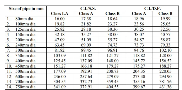
Pipe 1 = 700 mm pipe = 332.73kg/m (Considering C.I/S.S. pipe of Class A)
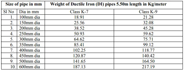
Pipe 2 = 200 mm DI pipe = 45.28 Kg/m (Considering DI pipes of Class k-9)
The weights are followed from Part-v of SOR.
Calculating the load on the bridge
(i) For 700mm dia pipe = 332.73 Kg/m
= 3.327 KN/m
the water load due to water in pipe = Area x Unit Weight
= pi x (0.35)^2 x 10
= 3.848 KN/m
Total Load for Pipe-1 = 3.327 KN/m + 3.848 KN/m
= 7.175 KN/m
(ii) For 200mm dia pipe = 45.28 Kg/m
= 0.425 KN/m
the water load due to water in pipe = Area x Unit Weight
= pi x (0.1)^2 x 10
= 0.3141 KN/m
Total Load for Pipe-1 = 0.425 KN/m + 0.3141 KN/m
= 0.739 KN/m
STAAD Pro. Analysis:-
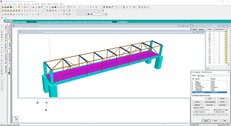
- The bridge has been created by considering the given data for the analysis.
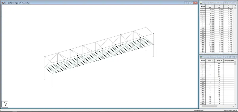
- Groups has been assigned for the structure according to diifrent types of sections as given.
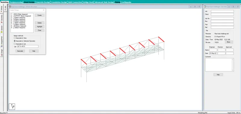
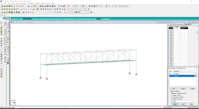
- Fixed Support has been assigned.
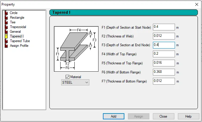
- For the section of a the following dimension has been considered as given.
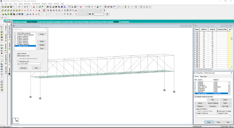
- All the materials has been defined as per the requirement. The pier size is considered as 1m x 1m & the thickness of deck slab is considered as 200mm thick.
- All the dimensions of the respective beam has been applied as per given.
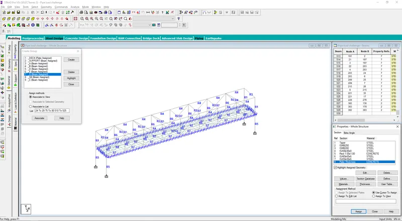
- The 3D render view of the structure.
- Load and Definitions
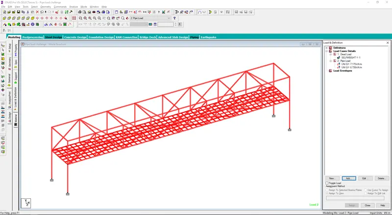
- Dead load is assigned for the whole structure.
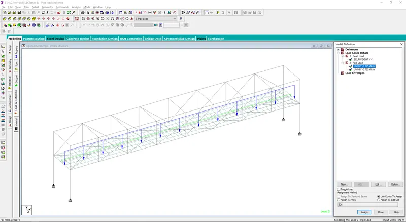
- Both the pipe load has been applied to the structure as calculated above and analyzed.
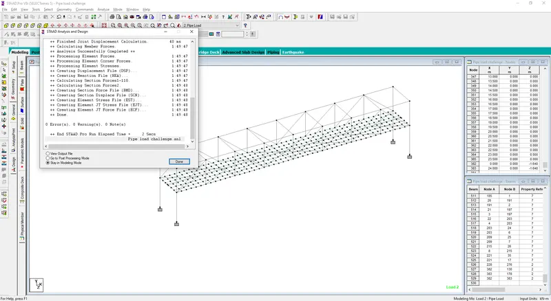
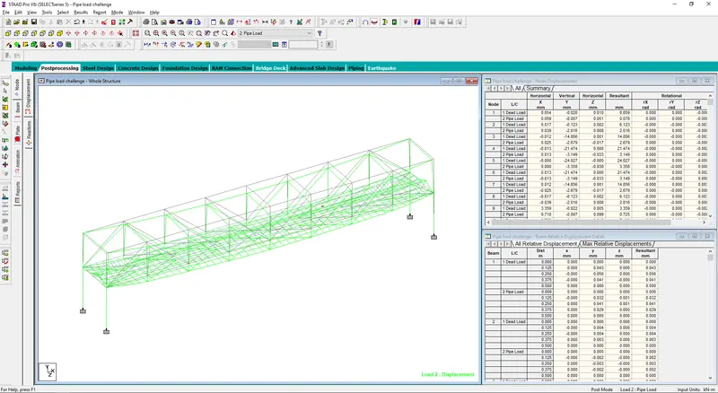
- Displacement
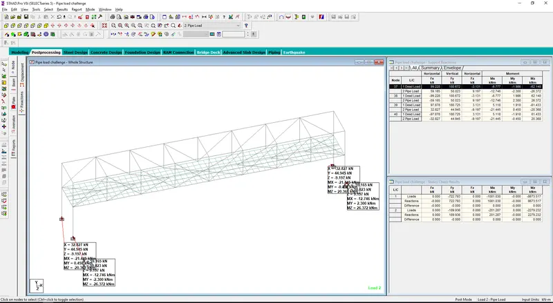
- End Reactions
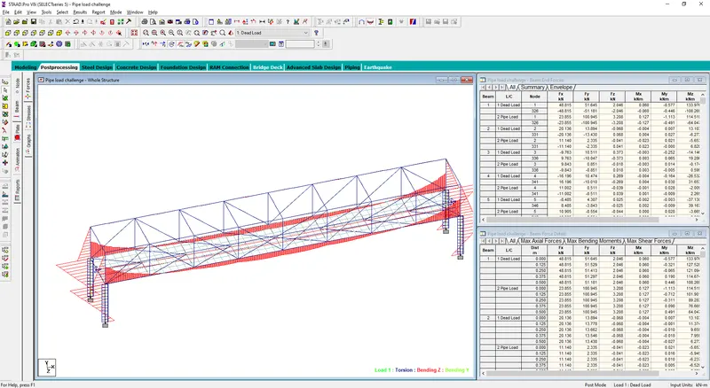
- Mx, My & Mz for dead load
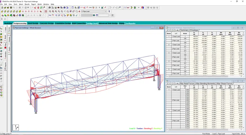
- Mx, My & Mz due to pipe load
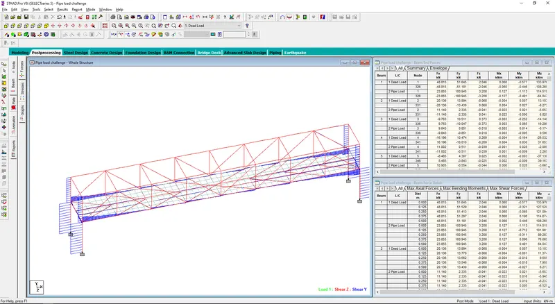
- Fy & Fz due to dead load.
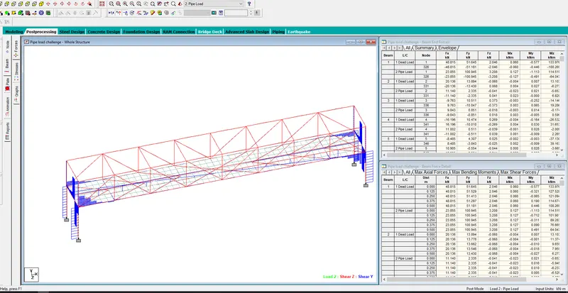
- Fy & Fz due to pipe load.
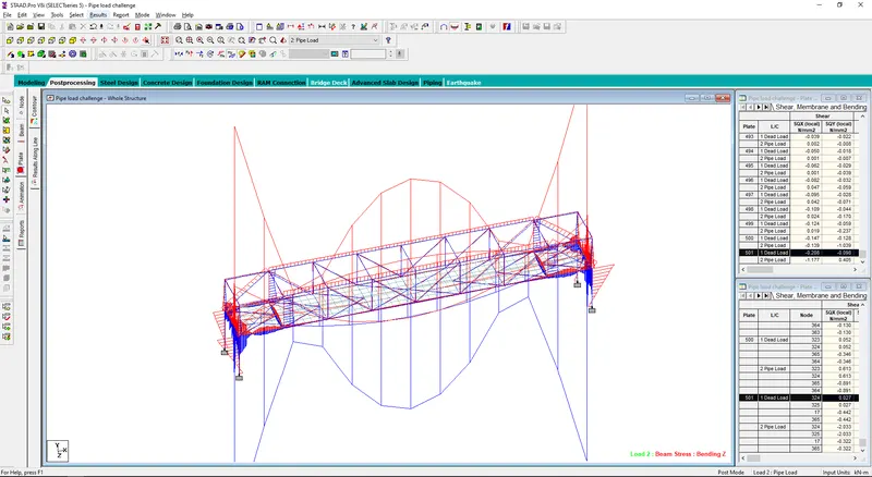
- Beam Stress value
- Plate stress due dead load on the structure.
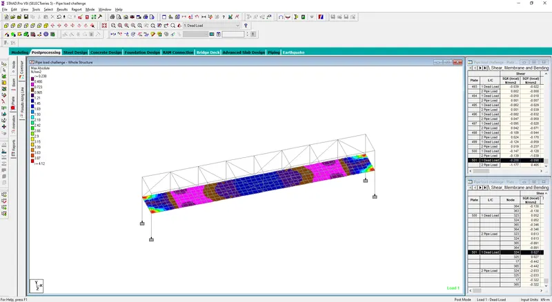
- Plate stress due pipe load on the structure.
