Week 3 Challenge
AIM :- Apply the IRS railway load on I Girder bridges in stadd pro.
INTRODUCTION:- This challenge is focusse on how to apply the IRS Railway load on the bridges using the stadd pro software. This study will provide the step by step procedure of designing the deck slab, girder and cross beam and the pier.
PROCEDURE:-
- Step 1 :- Analytical Modelling
- Firstly nodes were created. Then bridge were modelled
- Defining the section properties of the bridges like thickness of deck slab, girder, and cross beam. And then after defining the section properties of the pier
- Creating mesh side of 0.5 m x 0.5 m through out the length of the bridges.
- Creating fixed support at the base of pier
- LOADING:- First i apply the self weight of bridge as -1 by selecting the bridge. and then after that Irs railway live load (ELECTRIC TRAIN) is applied at suitable interval as per IRC-06 specifications.
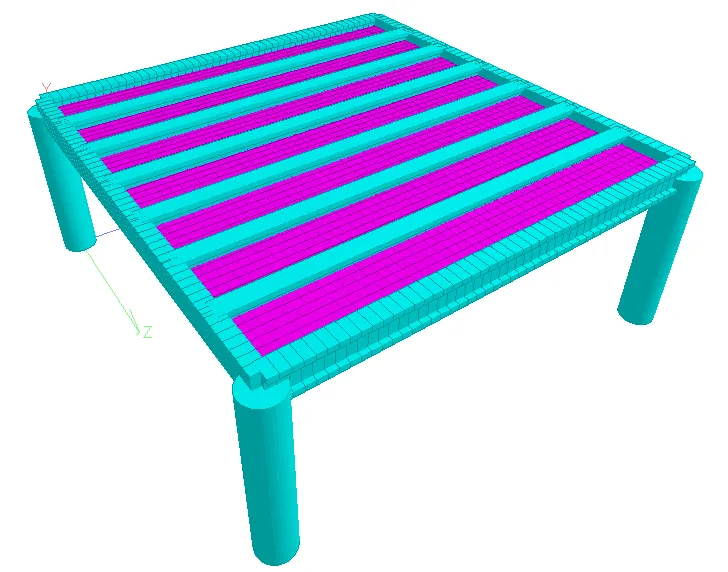
Figure 3D model of the bridge
STATIC CHECK:- Static check is ok as the difference between the load and the reaction is zero.
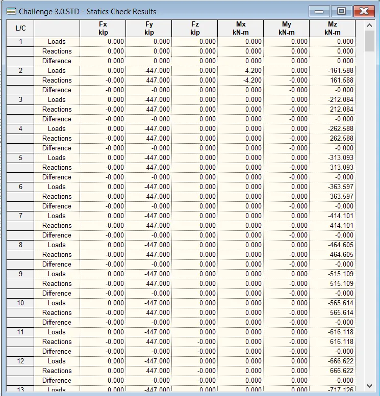
Figure Static check
REACTION:-
X = 80.374 KN
Y = 404.983 KN
Z = 10.969 KN
Mx = 8.273 kn-m
My = 1.599 kn-m
Mz = 63.285 kn-m
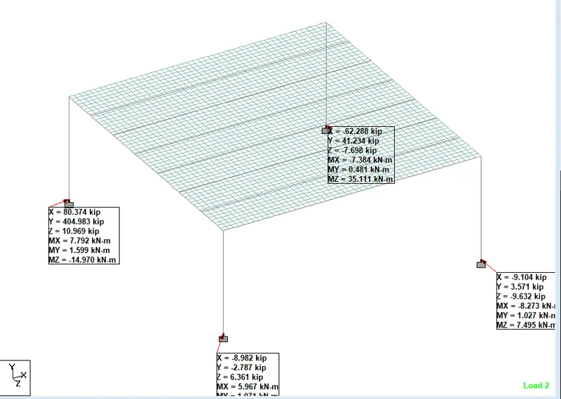
Figure Reaction
DEFLECTION :- Maximum deflection is of 2730.677 mm
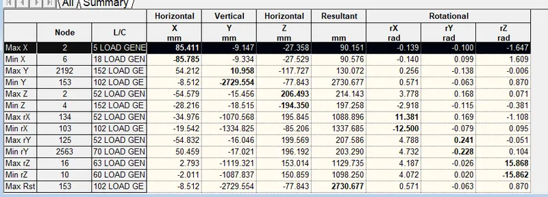
Figure Delection result
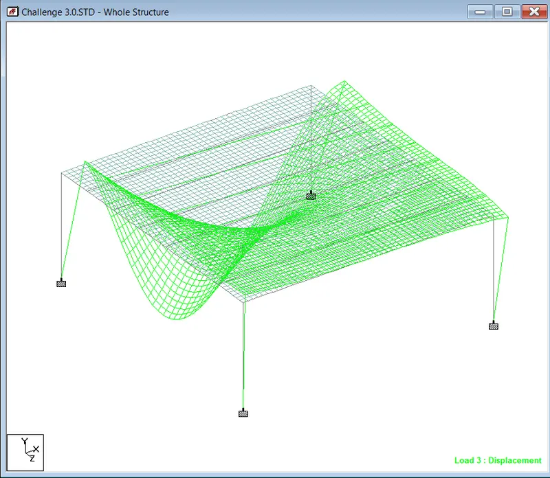
Figure Deflected shape of deck slab
PLATE STRESSES:-
Mx = 376.89 KN-m/m (maximum) and Mx = -51.829 KN-m/m (minimum)
My = 172.304 KN-m/m (maximum) and Mx = -117.878 KN-m/m (minimum)
Mxy = 92.107 KN-m/m (maximum) and Mxy = -92.233 KN-m/m (minimum)
Sqx = 1942.988 N/mm2 (maximum) and Sqx = -1942.025 N/mm2 (minimum)
Sqy = 1599.497 N/mm2 (maximum) and Sqy = -1852.541 N/mm2 (minimum)
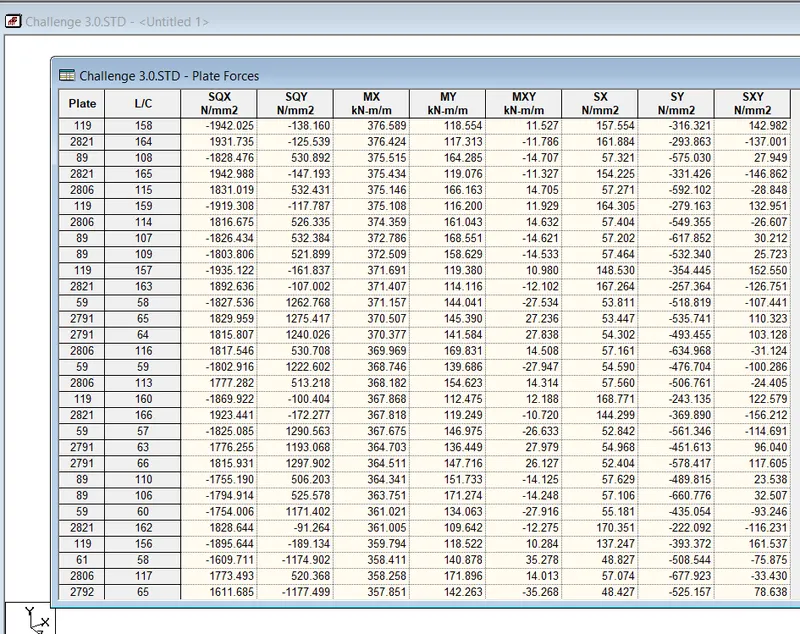
Figure Maximum moment (Mx)
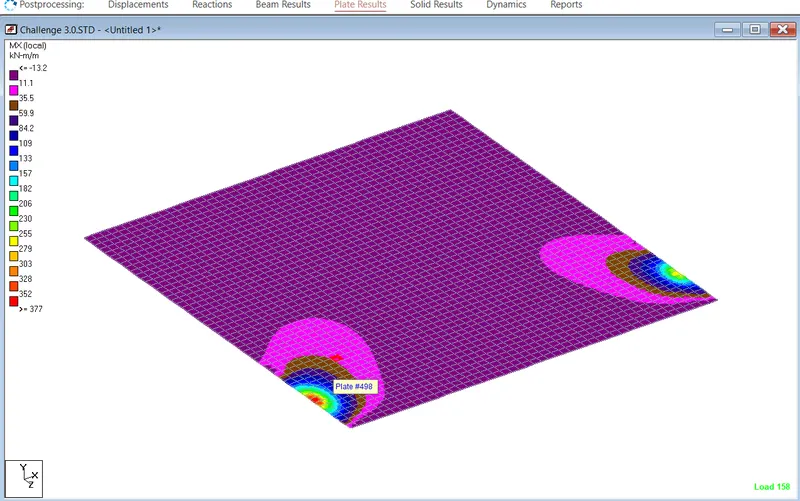
Figure Maximum plate stresses (Mx)
GIRDER FORCE CALCULATION
Mz = 263.777 KN-m
My = 2.231 KN-m
Shear -Y = 677.806 KN
Shear -Z = 26.768 KN
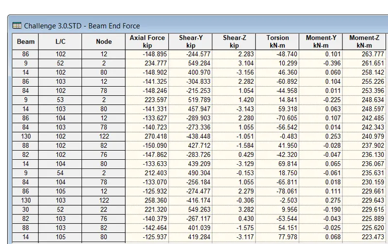
Figure Maximum moment (Mz)
CROSS BEAM
Mz = 141.797 KN-m
My = 3.373 KN-m
Shear -Y = 371.438 KN
Shear -Z = 39.378 KN
PIER
Mz = 138.160 KN-m
My = 268.787 KN-m
Shear -Y = 167.715 KN
Shear -Z = 323.663 KN