Week 6 Challenge
1)
ANS:-
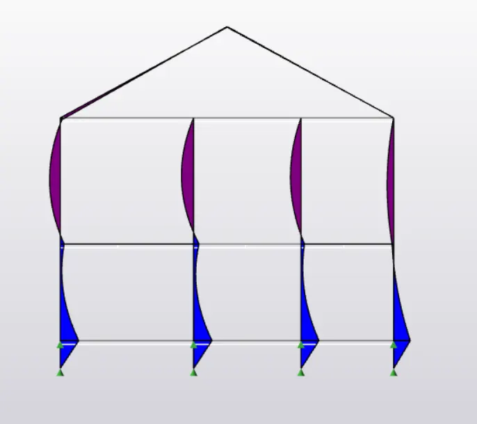
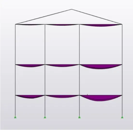
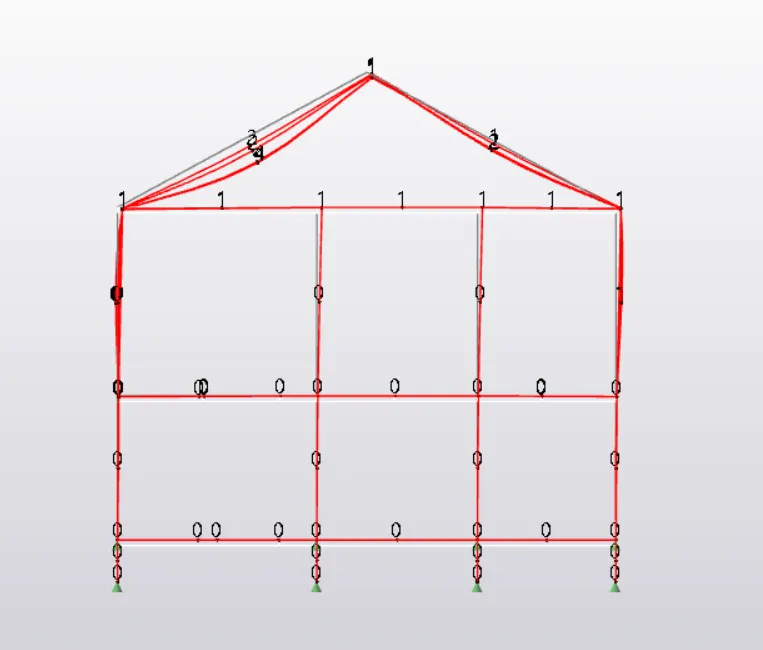
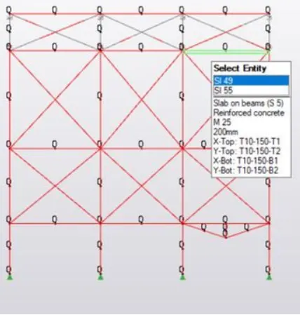
BENDING MOMENT:-
The bending moment can be defined as the bending effect which is caused due to any internal or external force.It is only of the important concept to be studied and bending moment play an important role in the strength of the structure. In our software TEKLA we have such advantages to finding the bending moment.Which is used for adjusting and analysing of the structure.It can be calculated as the algebric sum of the moment about the section of all forces acting on either sides of the section.
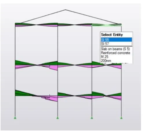
SHEAR FORCE:-
Shear force is a force acting in a direction that's parallel to a surface or cross section of a body,like the pressure of air flow over an airplane wing.It refers to the force acting along a surface.With in the beam,the shear force at any section is basically the algebric sum of the lateral forces acting on either side of the section.Calculation of the shear force is also important as it plays a vital role in analysis of the structure.
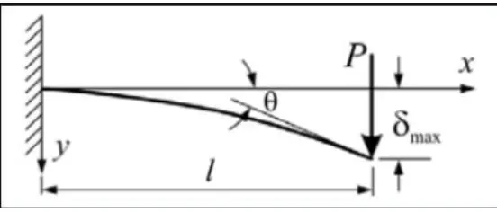
DEFELECTION DIAGRAM:-
In engineering, deflection is the degree to which a structural element is displaced under a load.The deflection distance of a member under a load can be calculated by integrating the function that mathematically describes the slope of the deflected shape of the member under that load.The degree of deflection increases with the distances between the supports or the amount of load applied on the member,The deflection diagram gives us a clear sketch about the load acting on the member.
2)
ANS:-
AIM:- Based on the analysis design the members and outline the thought process in selecting the member sizes along with the foundation design.
PROCEDURE:
- Open the saved file in the TEKLA software using the open icon present in the toolbar.
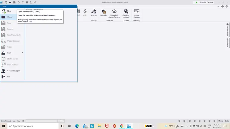
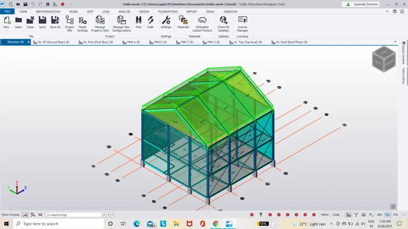
- Before performing analysis we have to check for some parameters for that let us select the settings icon present in analyse toolbar.
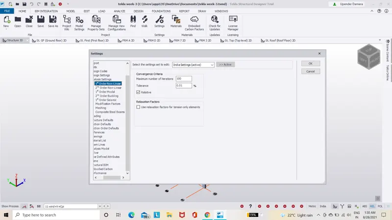
- A dialog box appears,click on 1st order linear and check for the number of iterations and tolerance and can modify if required.
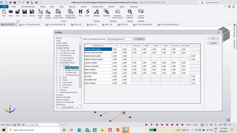
- Then checkfor modification factor, by default these are 1 but if there is any other factor change it to 1 and click ok.
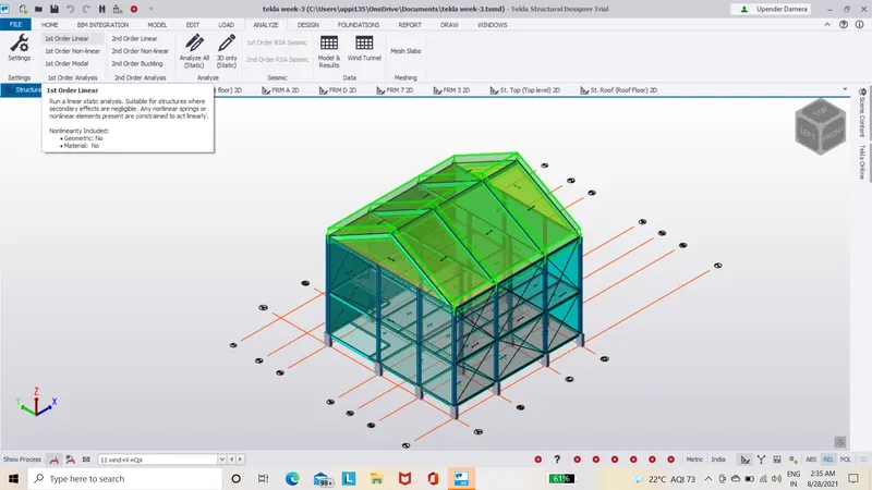
- Once the file is opened for analyzing the model,select analyse icon and click on 1st order linear from the options available.
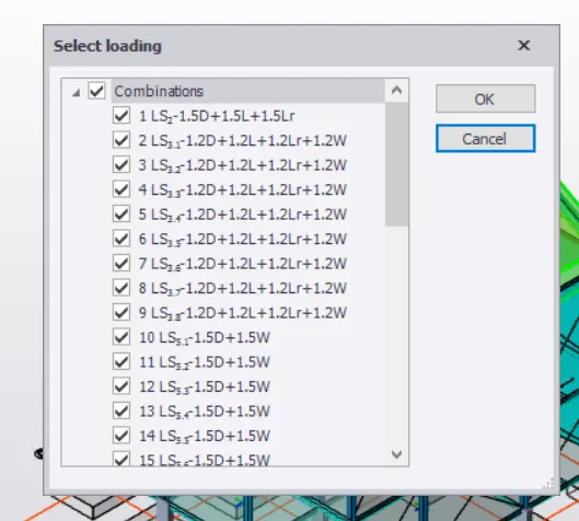
- Afṭēr̥ clickling on 1st order linear a dialog box appears where we have to select load cases and load combinations and click ok.
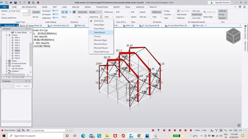
- In this way we can analyze a structure simply,for that make use of the result view and we will get any of the required parameters for the analysis that includes (axial force,shear major,shear minor,torsion,moment major,moment minor)can be accessed and also can check their values in different directions(X,Y,Z).
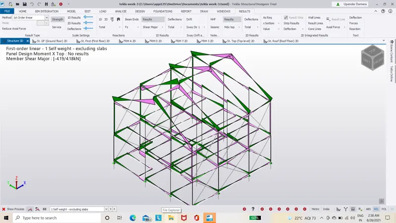
- Now by varying load combinations we can see different values of the parameters and we can modify the properties of the maerial for the worst-case values and modify its properties untill the load combinations will have satisfied the value of a parameter.
- Now let us check whether our analysis is right for this let us finish the above mentioned steps now and check whether our model satisfies the load combinations so once the above steps are done,select the solver options shown in the status menu of the project browser.
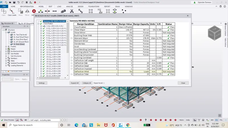
- From here we can say that the model satisfies all the load combinations.
- If is in any of the load combinations we can alter the properties of the model and analyze it once again.
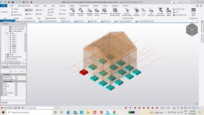
- Analysis of the model is done,NOw let us suppose design beam for that select the beam which you are designing then right-click on the selected beam based on the analysis.
- A large number of options will appear there we can select design/check member ,after selecting design member two options will appears select static.
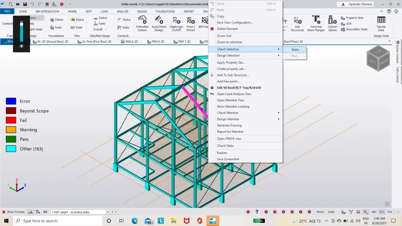
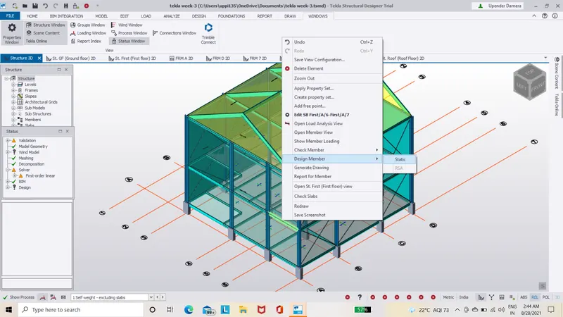
- A new table appears stating whether the member satisfies the load combinations,forces,bennding moment,axial force,etc.
- It is ok if the member passes the stated things but if it fails in any of the properties shown(Load combinations,forces,bending moment),the members properties must be modified.
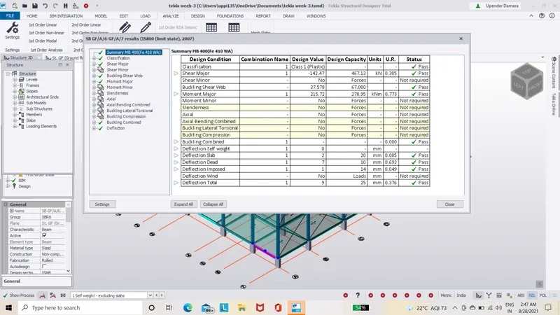
- As here the member clears all the tests tells us that the member is suitabe for the model and no need to change the member properties untill it clears all the tests ,similarly,we can do it with the remaining members.
- Now let us design the foundation for the model for this let us select the foundation icon present at the top.
- After selecting foundation a number of tyoe of modeling foundation will appear select anyone of them.
- So let us select pad base column option.
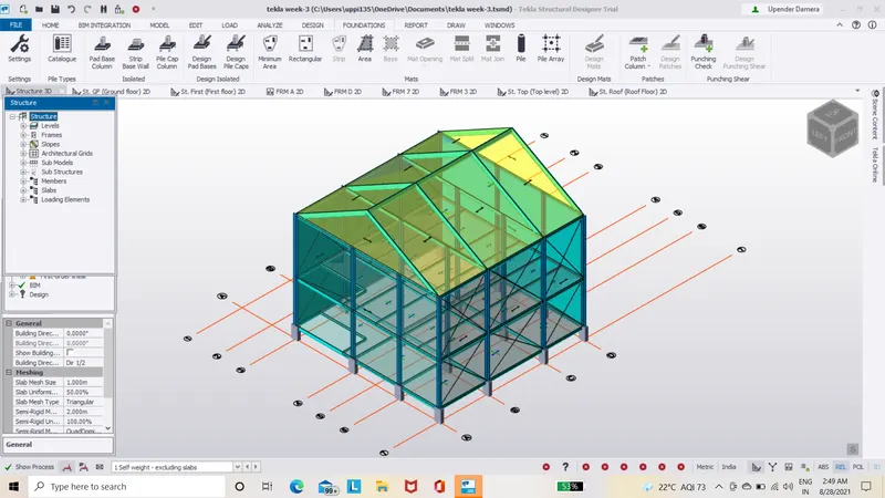
- Now with help of project browser go to base level and apply foundation to the column.
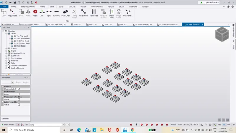
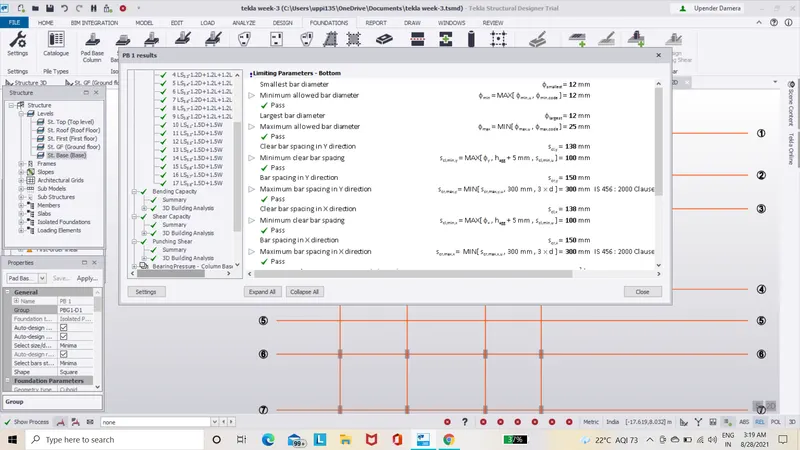
- Now right click on that foundation member and select design members followed by static option.
- A new window opens check that whether the foundation member passes all the tests if yes ok,but if it fails any tests we have to change the properties of the foundation member like its dimension,grade,etc.
- With the same properties let us apply the foundation for the whole model simply copying it from the edit toolbar and then it asks for reference node select it and paste it at desired locations.
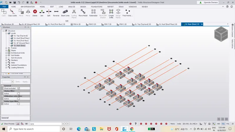
- We can use of scene content Icon for an ISOLATED view of the foundation.
RESULT:-
With the above steps we ahve successfully analysed the model and also Designed foundation member and Modeled the Foundation member to our model.
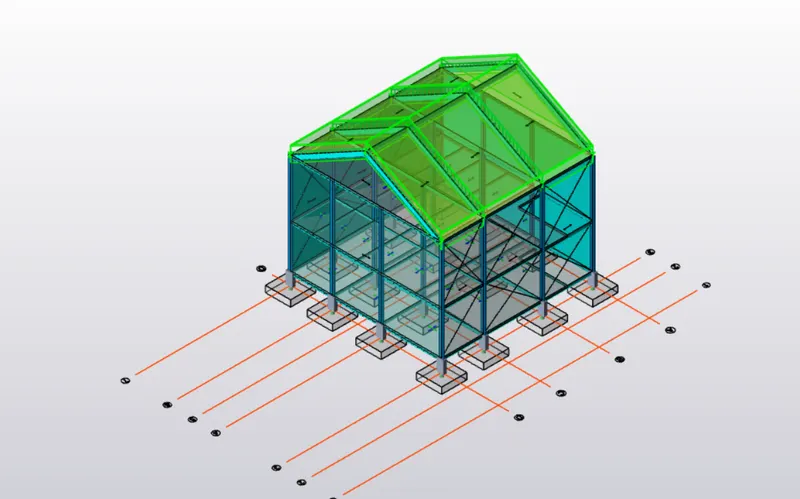
The final output of our model in 3D view as shown below.