Week 6- Challenge
Objective: To mesh the given HOOD component following given mesh quality criteria and then assigning thikness.
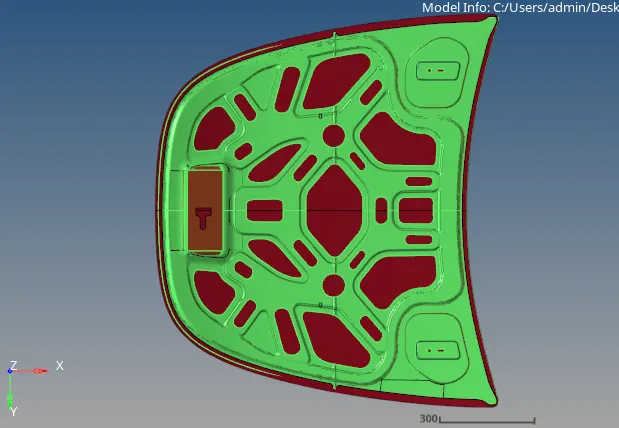
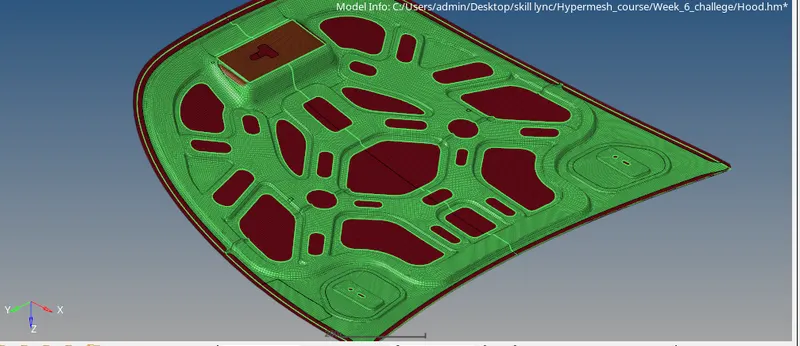
CAD Model Image:
Procedure:
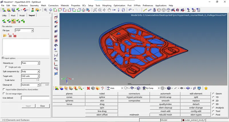
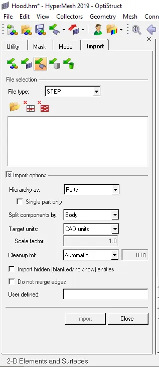
1. Import the model in the hypermesh using "Import Geometry" option.
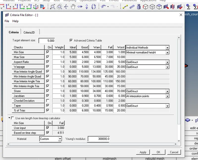
2. Once the model is imported in the hypermesh. Change the "Criteria File settings" and "Parameters file settings" according to the specified Quality criteria values. Theses options can be seen in the "Preferences" tab.
3. Now, using "Autocleanup" option in the "Geom" panel. For the specified mesh size of 5mm and selecting all the surfaces in the model perform autocleanup operation to toggle the unnecessary lines.
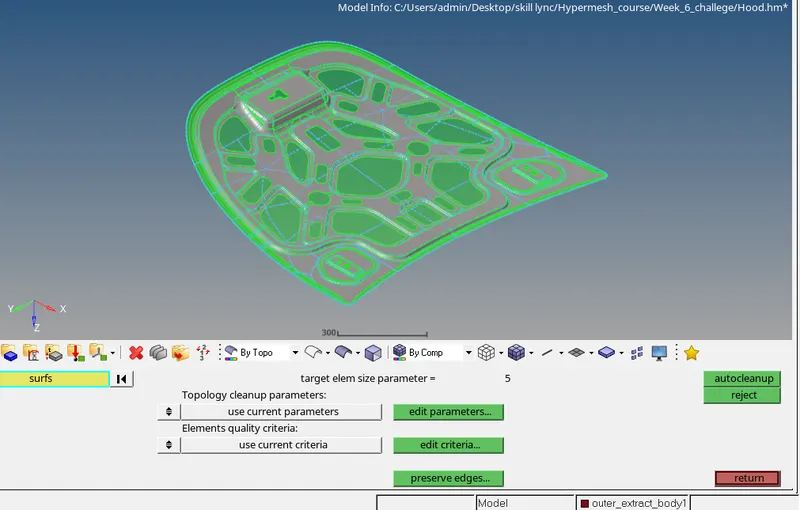
4. Once this is done. Now our model is ready for "MIDSURFACE Extraction". For performing the same go to "Geom" Panel and click on "Midsurface". Selecting extraction option as "SKIN OFFSET" and "result in current component". Now, go to auto extraction option and select all the surfaces to be midsurface, also select "Closed solid" option. then click on extract to extract the mid surface.
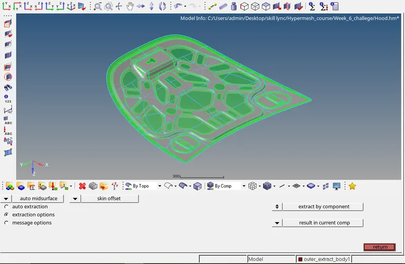
5. Further, perform "Autocleanup" on the extracted midsurface as well.
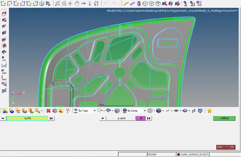
6. Now, delete the one half of the inner hood surface as it is symmetric along the x-axis. By doing this we'll have to work on less geometry and hence we can save time. Also, once the meshing is done on the one half of the model you can simply reflect it using "Reflect" option in the "TOOLS" panel.
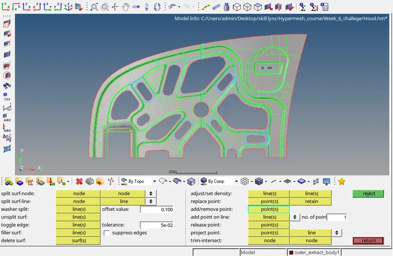
7. Further, we have to edit the surface using various options in the "QUICK EDIT" panel in order to get the proper mesh flow.
8. Finally, once our model is done with the Topology cleanup and the surface splitting we can proceed to mesh the component. For mesh we'll mostly used "AUTOMESH" option in the "2D" panel. In our case CRASH ANALYSIS has to be performed on the given model so we need mesh as "MESH FLOW/MESHLINES" for this we have to mention the desired element size i.e 5mm and elem type= Mixed and checking box next to align.
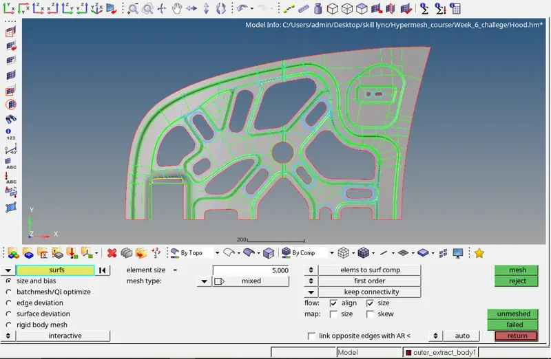
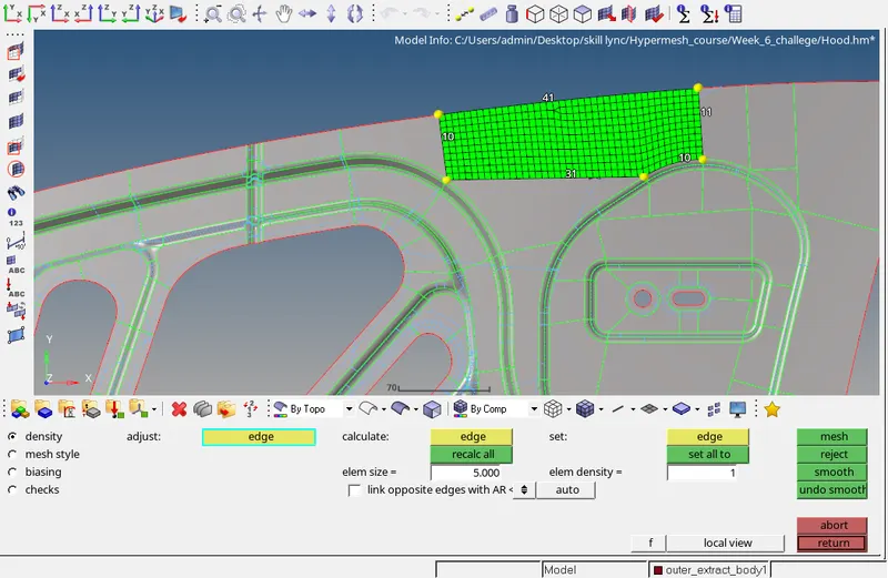
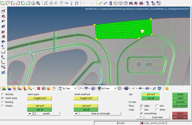
9. Once you click on the MESH, you will enter in to panel where you will have 4 options density, mesh style, biasing and checks. Density option can be used to change the node densities along the edges of the surfaces. Mesh style is used when you have a surface with proper shape such as rectangle, pentagon etc.
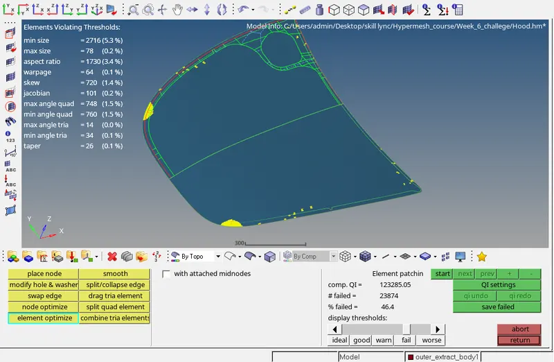
10. Once the mesh is generated, we have to also assure that the generated mesh defines allthe mentioned Quality criteria. For this 2 main options are used to check the failed elements in our meshed model. one is "check elems" and other is "qualityindex".
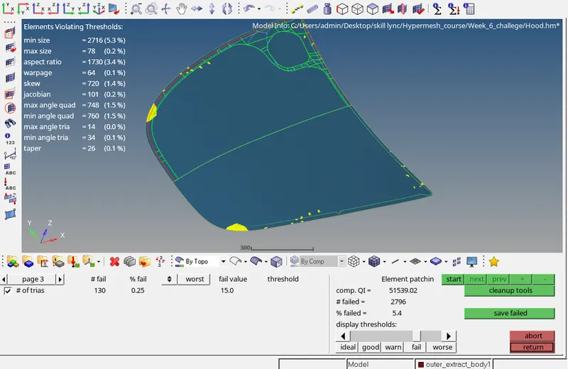
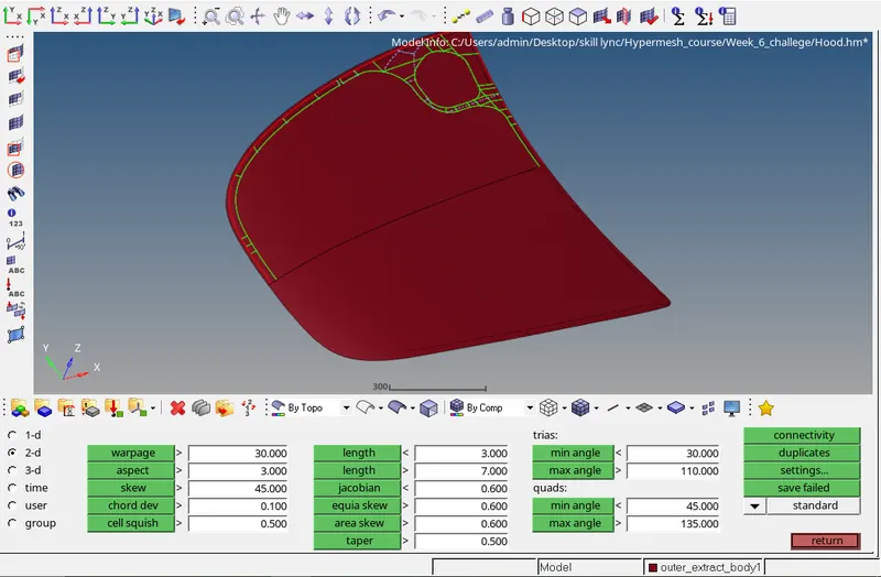
11. In the "qualityindex" option there is a option "Cleanup tools" which can we used to correct the any failed element in the mesh.
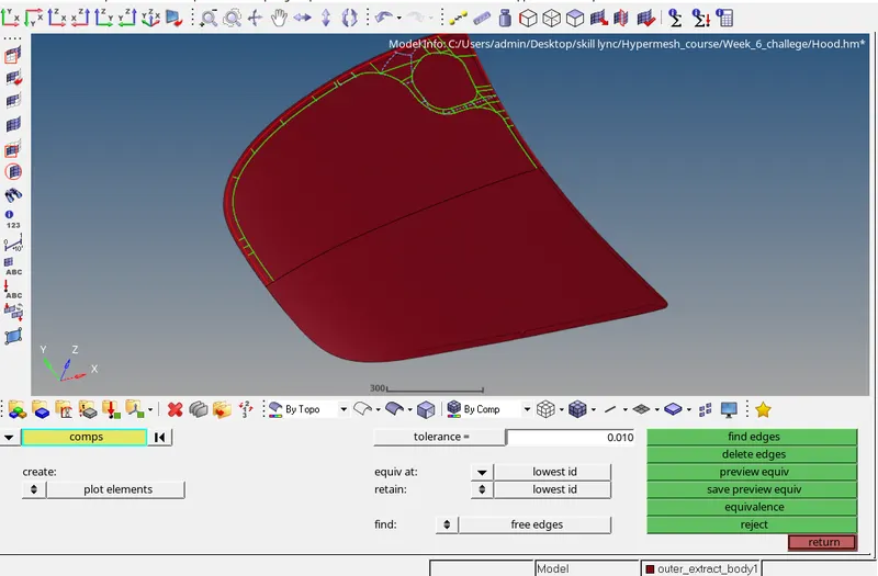
12. Once the mesh is generated and follows all the required Quality criteria. we can check or the "FREE EDGES" by clicking on the "edges" option in the "TOOLS" panel and by selecting the component you can find all the free edges in the mesh within the specified Tolerances.
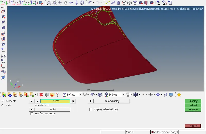
13. Yoy have to also check for the "NORMALS" and get all the normal directed towards the same direction.
Results: The given component is being meshed following all the given Mesh Quality Criteria and also being assigned thikness of 1.5 mm to all the components.
Final MOdel Image:
Isometric view:
Top View: