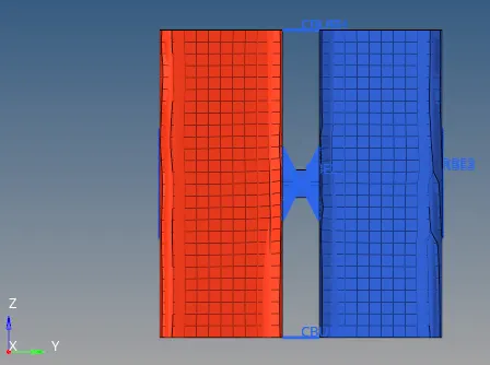
Defining 1D elements in Hypermesh.
Objective: Create 1D elements( Rods, Bars, Beams, Masses, Springs, Rigids and RBE3) on the following component with given cross-section and DOF.
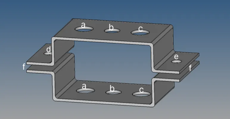
CAD model Image:
Procedure:
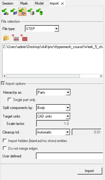
1. Importing model into the hypermesh using "Import Geometry" command.
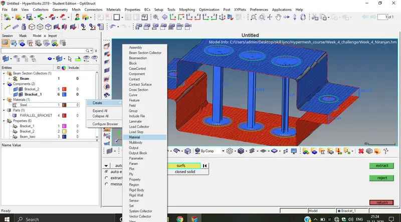
2. Next step is to extract a midsurface from the model. To extract a midsurface use "midsurface" command in the Geom panel. In the midsurface panel, use "Auto extraction" option and selecting Bracket_1 using Surf selection method. Atlast, Click on "extract" to create a midsurface for Bracket_1. Similarly, Create a midsurface for Bracket_2 using same procedure.

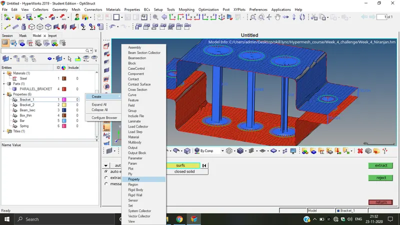
3. Further, Create material to be assigned to the extracted midsurface. For this right click on the "Model view" tab and scroll down to select "materials" in the create option. Once the material card is activated, Name the material as "Steel" and assign the default values to the E, rho and Nu.
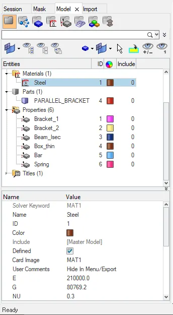
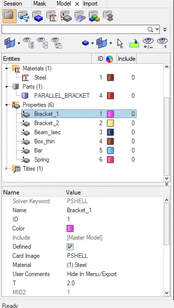
4. Further, Create a "Property" to be assigned to the extracted surface. For this right click in the Model view tab and scroll down to select "Property". Once the property tab is activated, rename it to "Bracket_1". Select the Card image as "PSHELL" and material as "steel". And assign thickness as 2mm. Similarly, Assign properties to Bracket_2.
5. Next step is to create a RBE2 and RBE3 elements at all the required positions. To create RBE2(rigids) elements, go to "1D" panel and select "rigids" panel. Now, click on create option. Further, select dependent node to "multiple node" and independent node to "Calculate node" and tick the boxes nextr to apply specific dof's. E.g In the (a) only translational degrees are transfered so boxes next to dof1,2,3 are checked.

6. To create a RBE3 elements, Go to "1D" panel and click on the "RBE3" to enter into the subpanel. Now, Click on the Create option, select dependent node to "Calculate node" and select a independent nodes using "By path" selection criteria. For (b) all the dependent dofs need to be transfered so check the boxes next to all the dofs. Further, select elem type as RBE3 and Click "Create" to create a RBE3 elements.

7. To create a Rod, Beam and Bar elements. First, create a beam section using "Hyperbeam" in "1D" panel. Using "Standard section" option and selecting Standard section library as "Hyperbeam" and Section type "Thinwalled Box". At last, Click create. This will get directed to the Hyperbeam window.

8. Once in the Hyperbeam section, then specify the dimension for lenght, thickness etc.
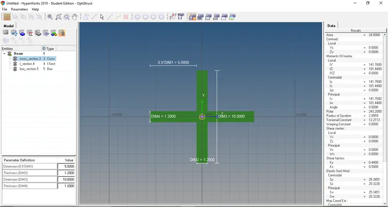
9. Once the sections are defined in the Hyperbeam, now properties are assigned to the sections defined.
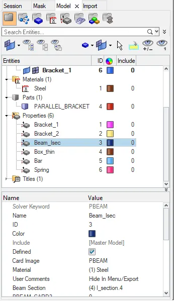
a. For the beam section, select Card image as "PBEAM", Material as "Steel" and Beam section as "I_section.4" form the list.
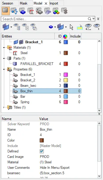
b. For Box section, Select card image as "PROD", Material as " Steel" and Beam section as "box_section.5".
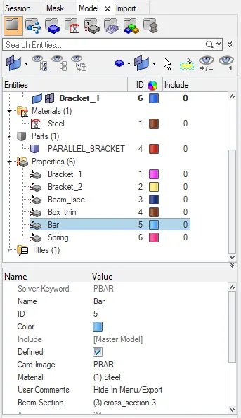
c. For bar section, select card image as " PBAR", MAterial as "Steel" and Beam selection as "cross_section.3".
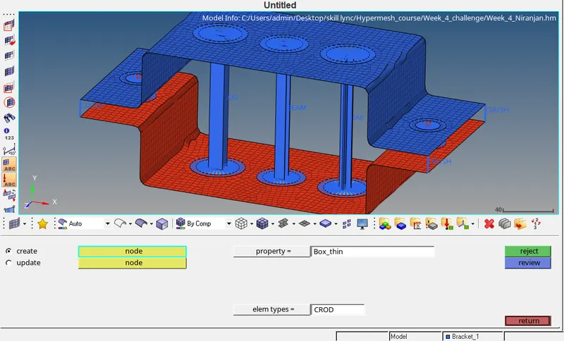
10. Once properties are defined for all the sections, Now create Rod element using the "ROD" option in the "1D" panel. Select the centre node for the rigids elements previously created. Select "Box_thin" as the property and elem types as "CROD".
11. Further, Beam and Bar elements are created using "Bar" option in the "1D" panel. Select the centre nodes of the rigids or RBE3 elements. Select "Beam_Isec" or "Bar"as the property and select elem types as " CBEAM" and "CBAR" respectively. Specify the orientation desired by selecting the nodes in that direction.
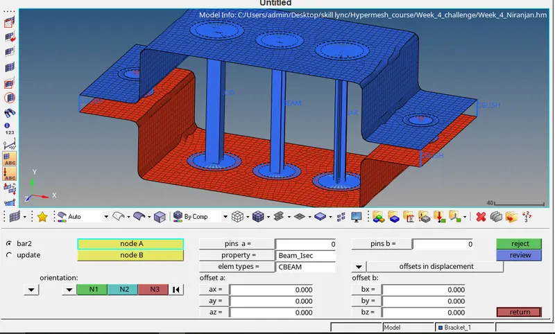
12. For defining mass to the perticular node, use "masses" option in the "1D" panel. Select the node where mass has to be assigned, Specify the property if necessary and selecting the elem type as "CMASS1" click on create to define a mass to the node.

13. For defining springs, Click on "Springs" option in the "1D" panel. Further, Select the nodes where spring element has to be assigned. Select suitable dof as in our case we selected dof2 because we need to transfer load in the Y-axis direction. Assign property "Spring" as previously defined and select elem type as "CBUSH".
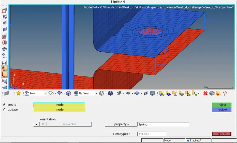
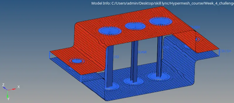
Results: All the given elements are assigned to the specified location in the model. Also, midsurface is extracted and meshed.
Final Model Image:
Isometric View:
Front View:
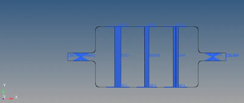
Top View:
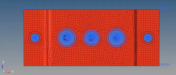
Right View: