Auto Cad Project -6: Drawing of cabinet ,floor plan ,kitchen ,column details and raft layout
Aim - To draw the cabinet ,floor plan ,kitchen ,column details and raft layout drawings :
Procedure :
Used tools in Auto Cad-
a. Line - To draw horizontal and vertical line of known distance- Command "L" -select the start point and end point.
b. Rectangle - To draw rectangle .Command "REC" - select the frist point - click on dimension then enter the value of length,press enter then value breadth of rectangle, press enter.
c. Offset - To darw lateral distance from a specified line . Command "O" - select the line ( specified line) then give the offset distance - click on the desired side where we need to make offset.
d. Trim - To delete the unwanted portion of a line/object . Command "TR" - select the line/object from which to be deteleted -enter -select the line/object to be deleted -enter.
e. Extend - To extend the line to another line at a distance . Command "EX" - select the line to which it has to be extended -enter - select the line to be extended -enter
f. Fillet - To join the corners or to curve the corners. COmmand"F" - give fillet radius ,if zero, it will from corner or it will form a curved shape with specified radius - select the two lines.
g. Horizontal construction line - Horizontal line which extends to infinity .Command "XL enter -H enter - click where we need to place the line.
h. Vertical construction line - Vertical line which extends to infinity . Command "XL enter V" - enter - click where we need to place the line.
i. Explode - To make a single selection object into diferent line segments. Command "EXPLODE" - select the object-enter.
j. Circle- to create a circle . Command "C" - select the centre point and give the diameter . By tan-tan -radius- select circle from tool bar and select tan-tan -radius methos - here two tangents and radius is given as input for creating circle.
k. Mirror- to crete the mirror object . Command "MI" - select the source object -select the base point- draw the mirror plane ,the mirror object will be created in opp side of the object with respect to the mirror plane . If we need to retain the source object click on 'no' for erase source object option.
l. Copy- To copy an object.Command"CO" , select the source object then select the base point -then copy the object to the required point .Click on "no" for erase source object ,if we need to retain the source object.
m. Divide - To divide a line into different line segments. Command "DIV" - select the line and give the number of line segments to obtain. enter
n. Point - To show the points for eg: to show the divided points after using Divide tool. Command "DDPTYPE" - seelct the style of point we want to display.
o. Text - To write the specification or information . Select from toolbar -single line - specify height only oneline text can be inputted
- multi line text - create the text box -specify height and insert the text.
p. Hatch - To hatch inside an object so that its function or what material it is made is known from the hatch for eg: hatching with brick symbol ,we can know that the wall is made with brick. Command "H" - pick a point inside the object - adjust the scale to required.
q. Dimension - To show the measurements .From the tool bar select the dimension tool and pick the 2 points between we need measurements.
r. Layer- To place each object in seperate layer so that , all the object in one layer will be selected with single selection and we can change the properties of all objects of the layer by changing properties of the layer. Select layer properties from the toolbar ,layer properties manager dialogue box apperas - we can create ,delete ,change the properties of layer.
Open Auto Cad in metric units ,if the dawing is in metric and imperial if the drawing is in feet and inches.
Set the limits and zoom all .Command -"Z" > "A".
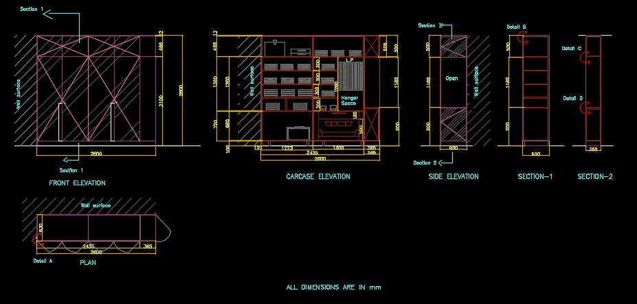
1. Cabinet drawing
Aim - To draw the plan , elevation ans section view of a cabinet
Procedure:
a. Drawing the plan :
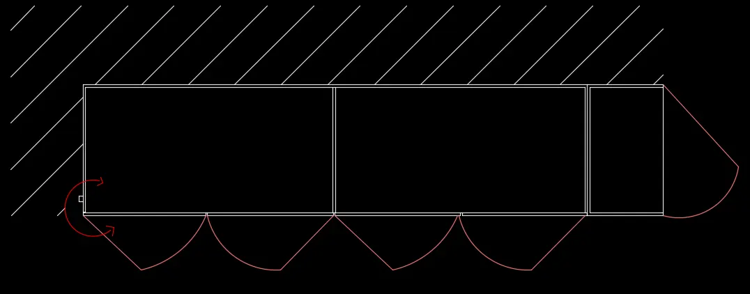
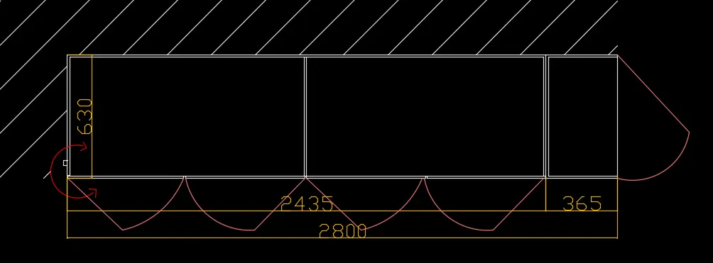
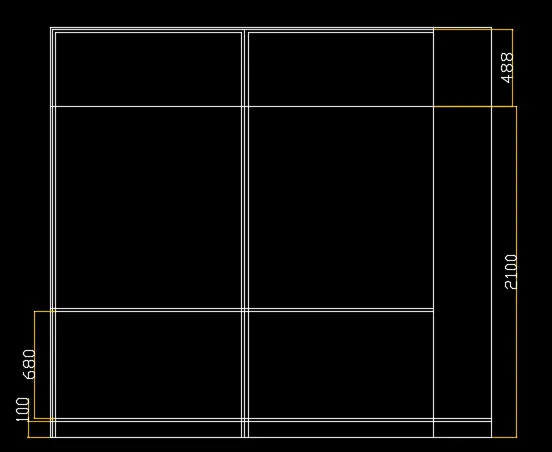
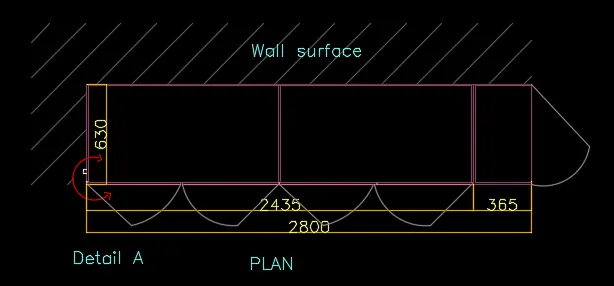
Draw a rectangle of size 2800 x630 mm Command "REC" -select dimensions give 2800 and 630 .
Give an offset of 12 mm inside to represent the thickness Command "O" - give the offset distance as 12mm.
Explode the rectangle Command "EXPLODE" - seelct the rectangle - enter.
Take offset from the right side of rectangle for a distance 365mm and also to two sides of 365mm by 12mm.
Take offset from 365mm at a distance of 1217.5mm ie the middle of 2435mm ,then also take ofset of 12mm to the left.
Draw a clamp on the left side inside the wall of 20 x20 mm.
Extend the bottom line to left most line and trim the joints in the upward portion.
For the door ,from 1217.5 mm draw a line to the centre on both sides by offset tool. Command "O" give offset distance as 608.75mm on both sides of line .
Trim the line such that the line in bottom portion only exist, then give offset of 4mm on both sides and delete the centre line on both the door portion.
Draw the doors by line and arc.
b. Drawing front elevation :
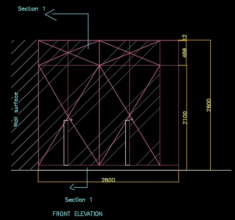
Project lines from the both ends of the plan view and also the 12mm line on left side with ortho on.
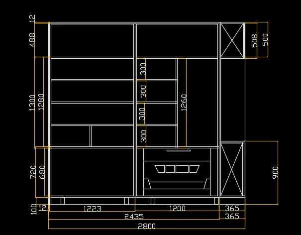
Draw a horizontal line as bottom and take offset of 2600mm from the horizontal line (total height of cabinet).
From bottom draw an offset of 100mm .Command"O"-offset distance 100mm.
From the bottom line take another offset of 2100mm to top and also 12mm thickness from top is also offseted.
Project the line of 365mm and 1217.5mm from the plan to the elevation. by extend or line tool . Command "EX" .
Also project the doors from the plan
Trim off the unwanted lines.
Draw the crossing lines by line tool to indicate the doors.
Draw the handles with line tool 80mm width and 995mm height.
With circle tool ,draw the locking section.
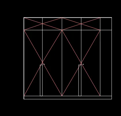
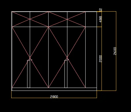
Also draw the section line 1-1.
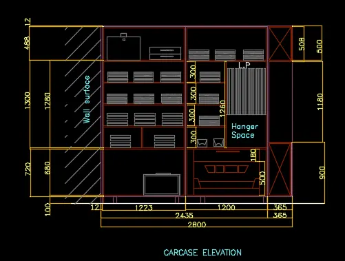
c. Drawing Carcase elevation:
Project the lines to side from the elevation - bottom line ,offset 100mm line ,2100mm line from the bottom and 12 mm thickness with ortho on.
Project the ends of the cabinet from the plan view
Take offset distance of 20mm(720-680=40;40/2=20) from the bottom horizontal line from 100mm offseted line ,side vertical line and top line from 12mm offseted line.
Take offset of 1223mm from the left end 12mm line so that the centre is market. take offset of 20mm on both sidesof this line.
Fillet the corners of the cabinet Command "F" - select the lines to be filleted ,enter.
To create inside partition:
Offset line at a distance of 680mm from the bottom 20mm offseted line then again offset 20 mm from that line.
Create offset of 300mm and 20mm as thickness till it meets the height of 2100mm.
Then divide the second portion of cabinet into half to create hanger space by offset ,offset distance as 580mm and also offset thethickness of 20mm.
Trim off the unwanted lines in the hanger space.
Divide the 1st shelf of 300mm from bottom ( left side )in the middle of it.
Create drawers in right portion : Offset 100mm from the two sides and bottom
Offset distance of 500mm from the bottom line.
In the right portion , draw a line from bottom as offset of 900mm and 500mm from top .
Draw the legs of cabinet by creating rectangle of 100x50 mm
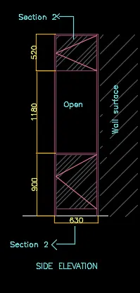
d. Drawing side elevation:
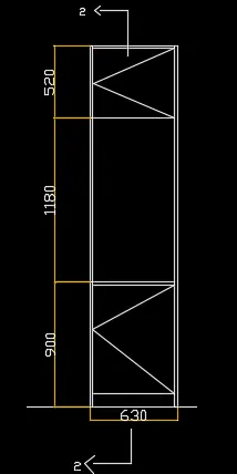
Project the height from the carcase elevation.
Draw a line of left side and offset 630mm for the right side.
Take offset of 20mm to show the thickness on the sides and top.
Take offsets from bottom as 100mm ,900mm ,20mm thickness and 1180mm to show the divisions.
Draw the section line 2-2.
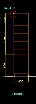
e. Drawing section 1
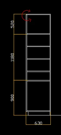
As section 1 is in elevation ,project the height from the elevation .
Giive an offset of 630mm which is the width and provide an offset of 20mm for thickness.
For the inside cabinets project lines from the carcase elevation of 100mm,900mm,300mm and 20mm as thickness .
Trim off the unwanted lines.
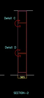
f. Drawing section 2
Project the height from the side elevation as the section is taken from the side elevation.
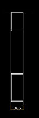
Give offset of 365mm as width
Give offset on the sides and top of 20mm
Project the 900mm line from bottom and 520mm line from the top
Dimensioning:
Click on the dimension in the tool bar .
Click onthe endoints of the lines we need to find the dimension
Dimension each plan, elevation,carcase elevation,sideview and section view.
Text :
Click on multiline text and select the text box give text height as 75 mm , 100mm and style as romans.shx Command "st"- click on style and select from the list.
Type the required text : plan, evelation, carcase elevation,side view,section 1 ,section 2 ,as 100mm height detail a,detail b, detail c, wall surface with 75mm height
To rotate text -select the text rotate give angle as 90 degree.
Hatching:
Wall surface and doors are hatched using hatch tool .Command "H".
Select ANS131 for wall surface with a scale of 50
Select ANS 134 scale 15 for doors surface.
Creating layers :
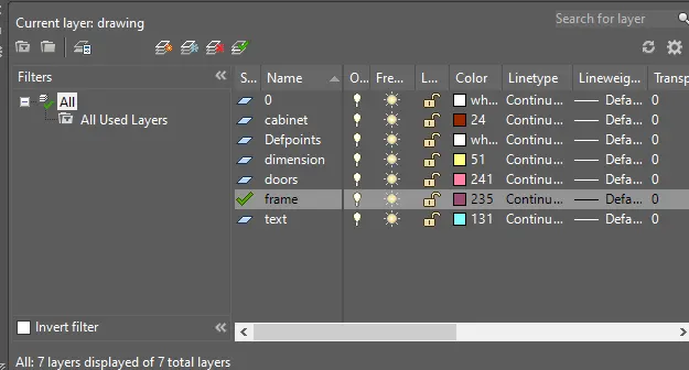
Click on layer property toolbar layer property manager is displayed - click on create new layer
Create 5 layers for frame,doors ,cabinet ,dimension,text and give colour for each layer for identification.
Select the frame of cabinet to frame layer doors to door layer,cabinet to vabinet layer dimensions to dimension layer and text to text layer.
Overwrite the door layer in plan for colour as it is not visible.
RESULT:
a. Plan
b. Elevation
c. Carcase Elevation
d. Side Elevation
e. Section-1
f. Section-2
RESULT: The cabinet drawing is shown :
2. Floor plan
Aim: To draw the floor plan of a building.
Procedure:
Draw construction lines Command "XL -H " and "XL -V" .
Give an offset of 230mm from the vertical line to draw the wall thickness.
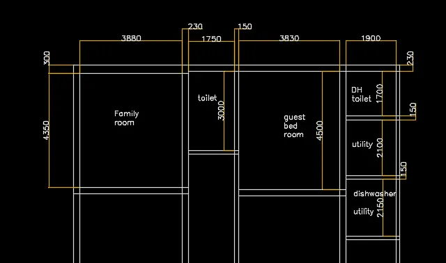
Drawing family room:
Give an offset of 3880mm from the wall thickness and offset of 230mm for the other side.
Draw an offset of 300mm as wall thickness from the horizontal construction line.
Draw another offset of 4350mm from the 300mm wall thickness for drawing the room.
Drawing toilet:
Give an offset of 1750mm from the right wall of family room ,also offset of 150mm to show wall thickness
Draw an offset of 250mm from the horizontal construction line for the wall thickness of toilet on outside side.
Draw an offset of 3000mm from the wall thickness ,so that the toilet is formed.
From the ofseted line ,draw 150mm for the wall thickness inside.
Drawing guest bed room:
Draw an offset from the wall of toilet at a distance of 3830mm.
Also offset the wall thickness of 230mm.
Offset 4500mm from the horizontal wall and also offset 230mm from that line.
Drawing DH toilet
Take offset from the guest bed room wall of distance 1900mm towards the right side.
Also offset wall thickness of 150mm from that line.
Offset a distance of 1700mm from the horizontal line ,wall thickness of 230mm .
Also offset a wall thickness of 150mm .
Trim off the rest of line of horizontal construction line.
Drawing utility room:
Take an offset of 2100mm downwards the wall of DH toilet
Also offset the wall thickness of 150mm.
Drawing dishwasher utility:
From the utility wall take an offset of 2150mm downwards andl also wall thickness of 150mm.
Drawing Kitchen:
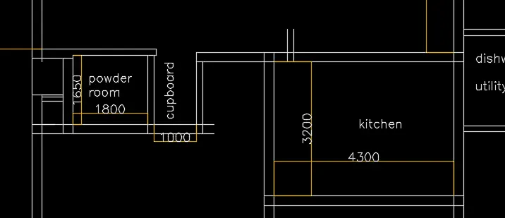
From the left wall of dishawasher utility room ,take an ofset of 4300mm to the left and wall thickness of 230mm .
From the wall of guest bedrrom draw an offset of 3200mm downwards and also wall thickness of 230mm.
Extend the topwall of kitchenupto a distance of 1462mm excluding wall thickness.
Drawing cupboard and powder room:
From the extended line, give a distanceof 1000mm for the cupboard and wall thickness of 150mm
Give an offset of 1800mm from the wall and also wall thickness of 230mm.
Make the above wall of powder room as 150mm.
Take offset of 1650mm fro that wall to the bottom.
Rest of the portion duct and open space is given.
Drawing living/dinning :
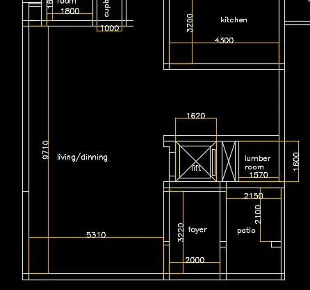
Draw an offset of 9710mm from the wall of powder room and also 230mm for the wall thickness.
Trim off the rest of the vertical construction line
Drawing foyer:
Draw offset from the wall of living room 2000mm to the right and wall thickness of 230mm.
Draw the width of room 3220mm offseting from the line (wall)extended from the living room
Offset the wall thickness of 150mm.
Again offset 230mm for the lift wall and extend it to right end.
Drawing Patio:
From the wall thickness of 230mm( extended lift wall) draw an offset of 2100mm downwards.
From the wall of foyer draw an offset of 2150mm and a wall thickness of 150mm on the right side.
Drawing lumber room:
From the wall of patio draw an offset of 1600mm towards backside.
Offset a wall thickness of 230mm .
To left side give an offset of 150mm as wall thickness
Drawing duct and lift:
Draw an offset of 500mm from the 150mm wall of lumber room and wall thickness of 230mm.
Take an offset of 1620mm from the wall for lift .
Draw the side walls and front walls of 230mm.
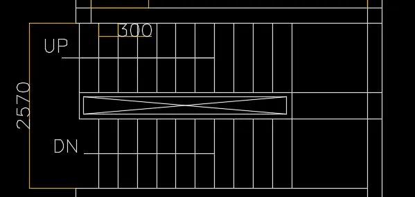
Drawing stairs : tread 300m and rise 150mm
Divide the stair room and offset 200mm to two sides by offset from the centre line.
Draw the first step ,then offset 300mm (tread) upto 11 divisions (12 steps in a flight),no of treads will be 11.
Rest of the portion forms landing ,draw 10 treads from the landing on other side of division.
Creating outside ducts and steps:
Create ducts at the front and backside
Steps on back with tread 350mm and side 250mm.
Create openings for doors and draw doors and windows:
Openings are given by trim command wherever door is required.
For D1 - 1000mm , D2- 900mm ,D3 -800mm , D4- 750mm ,D5 -700mm the width are trimmed for opening.
By creating hinge and with circle command circle with points (2 point method) with midpoint of hinges are drawn.
Vertical line showing the shutter is shown and the rest of the circle is trimmed off.
Create windows of size W1- 2700mm ,w2 - 2500mm , W3 - 900mm, W5-1000mm , W9-800mm ,V1- 800mm,V2-750mm
Fillet the corners and trimoff the unwanted lines.
Doors: Windows: Ventilators:
1. D1 - 1000 x 2000 mm 1. W1 - 2700 x 1500 mm 1. V1- 800 x 500 mm
2. D2 - 900 x 2100 mm 2. W2 - 2500 x 1500 mm 2. V2 - 750 x 500 mm
3. D3 - 800 x 2100 mm 3. W3 - 900x 1500 mm
4. D4 - 750 x 2100 mm 4. W5 - 1000 x 1500 mm
5. D5 - 700 x 2100 mm 5. W9 - 800 x 1500 mm
6. SD - 2256 X2100 mm
Dimensioning:
Select the dimension tool from toolbar and select the lines which the dimesion to be displayed.
Dimension all the rooms and wall thickness.
Also dimension the total length of each side.
Text :
Text is written with multiline text .
Select multiline text- draw the text box- make text height as 300mm and style as romans.hsx. Command "ST" .
Give names and measurement of each room.
Give the designation of doors and windows.
Layers:
Click on layer properties in toolbar layer properties manager dialogue box appears - click on create new layer.
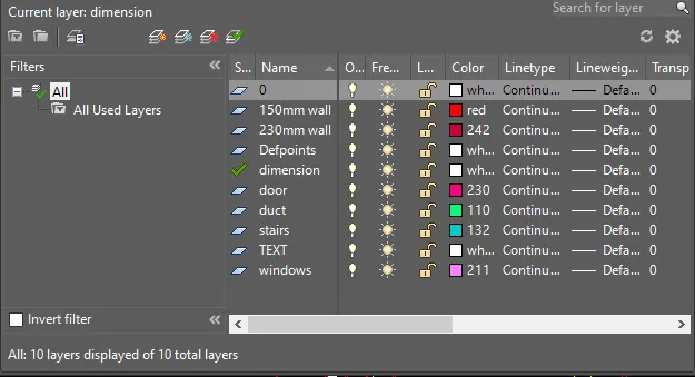
Layers are created for 230mm wall , 150mm wall, doors,windows,ducts,stairs,text .
Different colours are assigned to different layers for identification.
Each of the items are selected and are assigned respective layers.
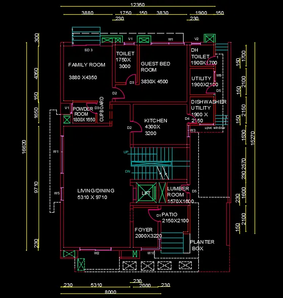
RESULT: The floor plan drawn is shown:
3. Kitchen layout:
Aim : To draw kitchen layout
Procedure:
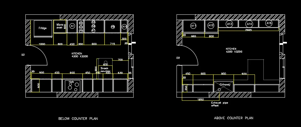
Below counter plan:
Drawing the wall
Draw a rectangle of 4300 and 3200mm
Draw offset 230mm as wall thickness towards outside.
Drawing left cabinet and fridge:
Fridge is drawn on leftmost side by rectangle tool.
Take an offset of 1000mm and start drawing slab showing cabinet below
Offset 600mm for cabinet below for microwave oven ,give an offset of 20mm to show the partition of cabinet below.
For width of cabinet give 600mm offset , give 20mm inside offset and 10mm offset for thickness.
From 600mm offset of microwave cabinet ,give an offset of 450mm for A1.
From that give 300mm offset A2,A3 ,A4 .
From 300mm offset give another offset of 900mm for A5,A6,A7.
Draw 35mm offset from the right side for the hinge and give thickness of 20mm.
From the 35mm draw an offfset of 300mm towards left for the cabinet below sink drain and rest will be cabinet below sink. (assumed 300mm from right).
For all the divisions of cabinet ,take 20mm on both side to show the thickness.
To create doors, extend the line of all the divisions and give 10mm offset on both sides in the 10mm offset given for thickness.
Erase the extended line and trim the horizontal line for opening of doors.
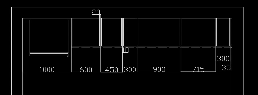
Drawing right cabinets and hob:
Give 35mm offset from the left and create a hinge.
For width of cabinet give 600mm offset , give 20mm inside offset and 10mm offset for thickness.
From 35mm give 900mm offset
Give an offset of 450mm from the 900mm offset
Again offset a distance of 900mm
Offset a distance of 450mm three times from the respective preceeding offset
From right side offset 35mm for hinge and rest distance will be 630mm which shows the top of cabinet.
Offset a distance of 20mm on both sides of all offseted lines ( from all divisions).
To create doors, extend the line of all the divisions and give 10mm offset on both sides in the 10mm offset given for thickness.
Erase the extended line and trim the horizontal line for opening of doors.
Extend the centre line to the thickness for 3 cabinet from the left.
Hob is drawn by rectangle and circle tool in the plan of third cabinet from the left.
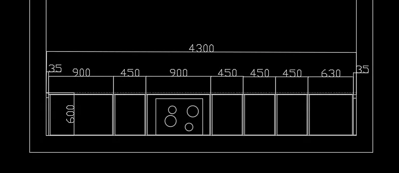
Drawing snack counter:
Offset a distance of 700mm from the left side of wall and 900mm from the 600mm width of cabinet.
Fillet the end of the snack counter with fillet radius 10mm.
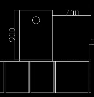
Above counter plan:
Copy the wall of the below counter plan as the dimesions are same.
Drawing right side counter :
Draw a width of 350mm from the wall , to inside offset 20mm to show the thickness.
Offset a distance of 35mm from the left side of wall.
Next offset 450mm for the top of the cabinet
Offset 900mm 3 times for the next cabinets.
From the right side offset 35mm ,the rest distance of 1095mm will be the cabinet.
For the second 900mm offset ,draw rectangle and from a distance of 1650mm from the left side of wall ,draw a circle for the chimney.
For rest of the offset ,offset 20mm on both sides for the thickness.
From the plan, the below counter and snack counter will be also seen , draw that and show it in light colour as same distance as in the below counter plan.
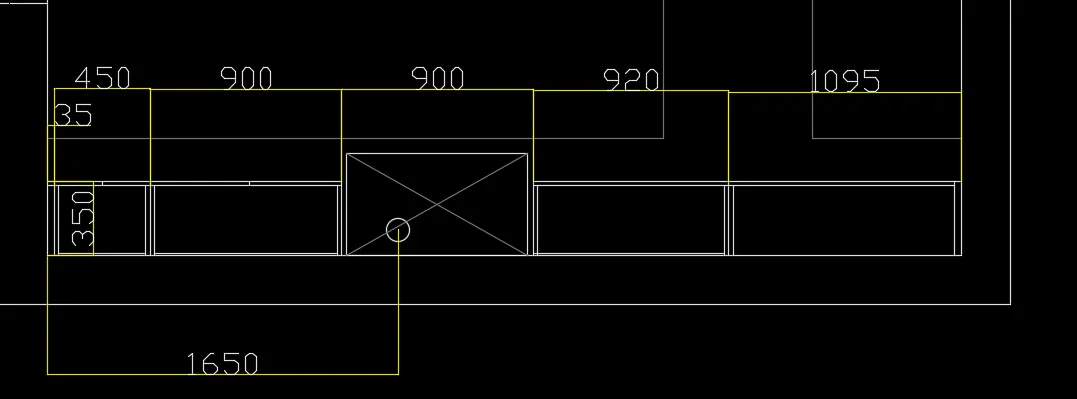
Drawing left side counter:
From the left side wall take 35mm offset to draw the hinge.
Draw 600mm offset as width from the horizontal wall.
Draw 10mm offset to show the door .
Draw an offset of 38 mm from the 10mm door for the cabinet.
From 35mm hinge offset 965mm to the right. A11
From that offset 600mm for the next cabinet A12.
Take offset of 350mm from the horizontal wall as width of next cabinets.
Offset a distance of 35mm from the right
The rest distance is 2665mm which is divided into 3 equal parts .A13,A14,A15.
Then offset 20mm on both sides of divisions and also 20mm in front for doors
Offset 10mm in backside for showing thickness.
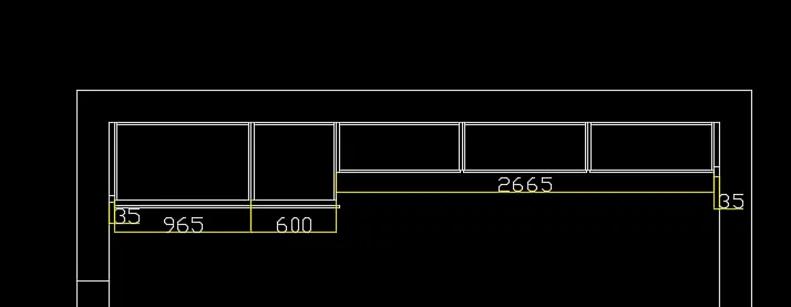
Drawing doors,sliding doors and windows:
Create door on the left wall of the kitchen on both the plan.
Consider door of 900mm width. Trim 900mm from the wall thickness.
Draw a hinge of 20mm , and draw circle from centre of one hinge to another
Draw vertical line from one hinge to the circle to show the opening .
Trim off the rest of circle.
To draw the window,consider window of width 900mm .
From the 600mm width of cabinet ,take an offset of 900mm ( in line with the snack counter).
Draw the hinges and shutters of windows by using line tool.
Copy it to the above counter plan
To draw sliding doors take 200mm offset from the window.
Give an opening of 900mm take offset of 900mm from the 200mm offset.
Draw the shutters of the sliding door.
Copy it in the other plan also.
Text and dimensioining:
Dimension all the objects by dimension tool in the toolbar.
For text , select multiline text size -75mm style romans.shx .Command "ST".
Write all the text in respective places like fridge, hob, cabinet number etc.
RESULT:
Kitchen layout drawn is shown below:
4. Column details:
Aim: To draw column details
Procedure:
Open Auto Cad and set it to imperial ,as the drawing is in feet and inches.Set the limits -zoom all
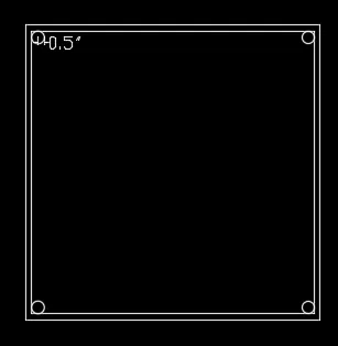
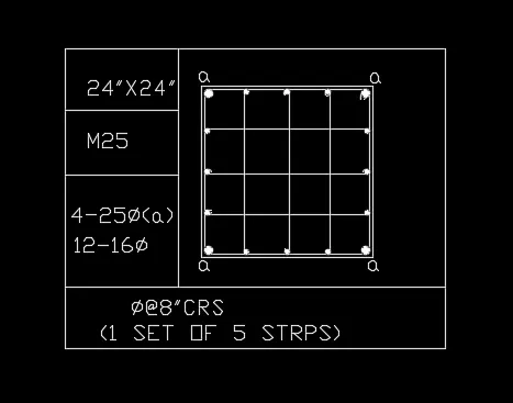
a.Drawing P1: Column of size 24" x24" having 4 bars of 25mm dia and 12 bars of 16mm diameter and connected by 8mm diameter stirrups.
Create rectangle by rectangle command with dimensions 24" x24" .
By offset command create an offset of 0.5" to show the column outline.
Explode the inner rectangle so that the lines can be selected seperately.
Drawing reinforcement for P1:
Draw circle with tan -tan radius method with tangent as the two sides of column and 0.5" radius .
As the four corners are having 25mm dimaeter bars, mirror the circles by command "MI" and drawing horizontal and vertical planes.
Drawing 16mm dimaeter 12 bars
Using divide command divide the leftmost line of the column by command "DIV" - enter the no: of segments as 4
By Command "DDPTYPE" seelct the point so that it is visible.
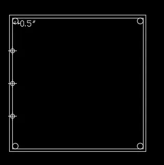
Now create a circle with centre radius method with radius as 0.31"(16mm dia bars) and place the side of circle with centre of point.
Copy the two circle and place it in the position of the points
Mirror the 16mm diameter bars by drawing vertical mirror plane. and delete the points created.
Again divide the horizontal lines into 4 segments and copy the circle and place the side of circle in the centre of the point.
Connect the bars by 8mm stirrups for that draw line with line command connecting the 16mm diameter bars.
Draw the rings by arc- 3 point method , and mirroring it.
Fillet the corners of the colum outline with filet radius as 0.5".
Use donout command to fillthe circle Command "DO" - specify the inner dimaeter as 0 and outer diameter as 0.1" for 4 corner reinforcement and 0.62" for inside reinforcement -specify centre of the donout , it gets filled.
Mark "a" for in between reinforcemnet to indicate it as 25mm diameter by singleline text with text height 2".
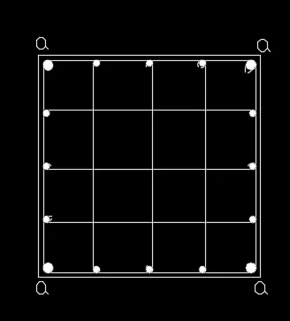
Create a column to indicate the size of column, grade of concere and reinforcemnt details. By multiline text with text height 2" and style txt .shx .
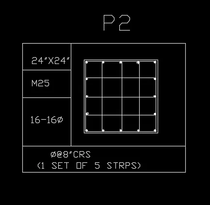
b. Drawing P2: Column of size 24' x24' having 16bars of 16mm diameter connected by 8mm diameter stirrups.
Create rectangle by rectangle command with dimensions 24" x24" .
By offset command create an offset of 0.5" to show the column outline.
Explode the inner rectangle so that the lines can be selected seperately.
Drawing reinforcement for P2:
Draw circle with tan -tan radius method with tangent as the two sides of column and 0.31" radius .(16mm diameter).
As the four corners are having 16mm dimaeter bars, mirror the circles by command "MI" and drawing horizontal and vertical planes.
Using divide command divide the leftmost line of the column by command "DIV" - enter the no: of segments as 4
By Command "DDPTYPE" seelct the point so that it is visible.
Copy the circle created such that the end of circle is in centre of the point.
Mirror the 16mm diameter bars by drawing vertical mirror plane. and delete the points created.
Again divide the horizontal lines into 4 segments and copy the circle and place the side of circle in the centre of the point.
Connect the bars by 8mm stirrups for that draw line with line command connecting the 16mm diameter bars.
Draw the rings by arc- 3 point method , and mirroring it.
Fillet the corners of the colum outline with filet radius as 0.31".
Use donout command to fillthe circle Command "DO" - specify the inner dimaeter as 0 and outer diameter as 0.31" -specify centre of the donout , it gets filled.
Create a column to indicate the size of column, grade of concere and reinforcemnt details. By multiline text with text height 2" and style txt .shx
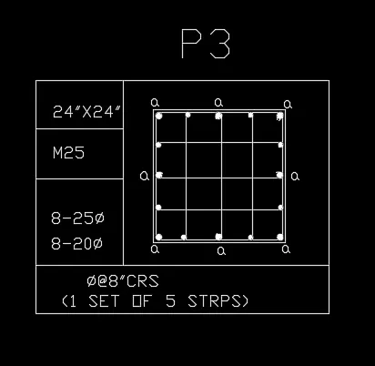
c. Drawing P3: Column of size 24" x24" having 8 bars of 25mm dia and 8 bars of 20mm diameter and connected by 8mm diameter stirrups.
Create rectangle by rectangle command with dimensions 24" x24" .
By offset command create an offset of 0.5" to show the column outline.
Explode the inner rectangle so that the lines can be selected seperately.
Drawing reinforcement for P3:
Draw circle with tan -tan radius method with tangent as the two sides of column and 0.5" radius .
As the four corners are having 25mm dimaeter bars, mirror the circles by command "MI" and drawing horizontal and vertical planes.
Using divide command divide the leftmost line of the column by command "DIV" - enter the no: of segments as 4
By Command "DDPTYPE" seelct the point so that it is visible.
Copy the 25mm diameter circle 0.5" radius to the middle vertical and horizontal bars.(2nd division of the point both vertical and horizontal)
Now create a circle with centre radius method with radius as 0.39"(20mm dia bars) and place the side of circle with centre of point.
Copy the two circle and place it in the position of the rest of the points
Mirror the 20mm diameter bars by drawing vertical mirror plane. and delete the points created.
Again divide the horizontal lines into 4 segments and copy the circle and place the side of circle in the centre of the point.
Connect the bars by 8mm stirrups for that draw line with line command
Draw the rings by arc- 3 point method , and mirroring it.
Fillet the corners of the colum outline with filet radius as 0.5".
Use donout command to fillthe circle Command "DO" - specify the inner dimaeter as 0 and outer diameter as 0.1" for 8 25 mm reinforcement and 0.78" for rest of the 8 reinforcements -specify centre of the donout , it gets filled.
Mark "a" for in between reinforcemnet to indicate it as 25mm diameter by singleline text with text height 2".
Create a column to indicate the size of column, grade of concere and reinforcemnt details. By multiline text with text height 2" and style txt .shx .
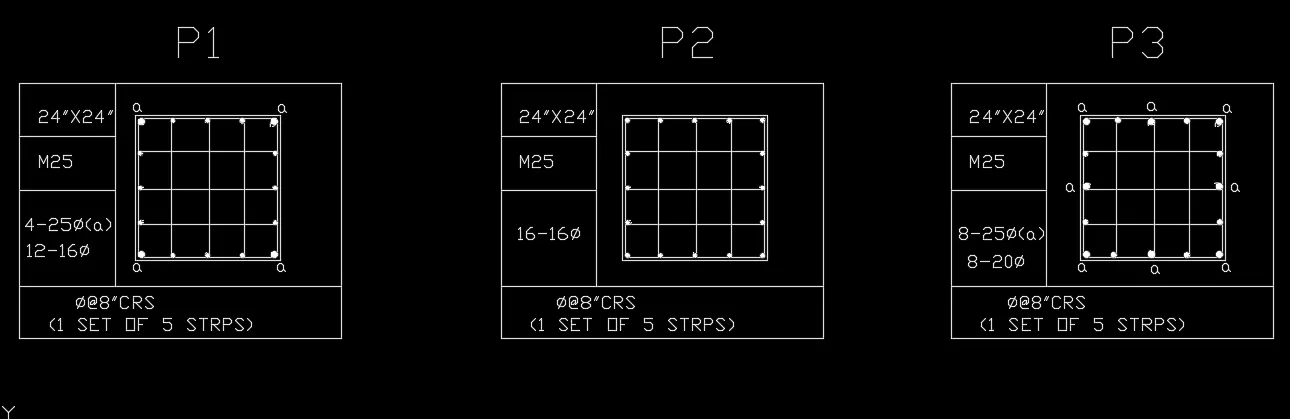
RESULT:
All the three column details are drawn
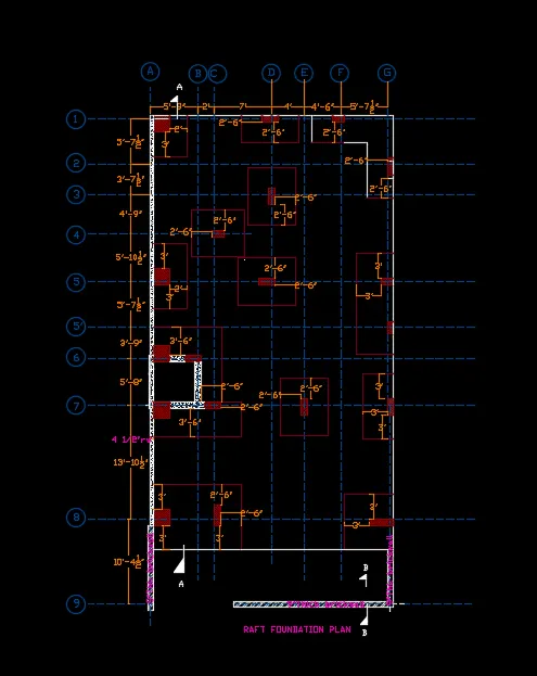
5. Raft Layout
Aim : To draw raft layout
Procedure:
Open Auto Cad and set imperial units and change the units as architectural so that the dimensions are in fractions of feet and inches.
Drawing grid lines:
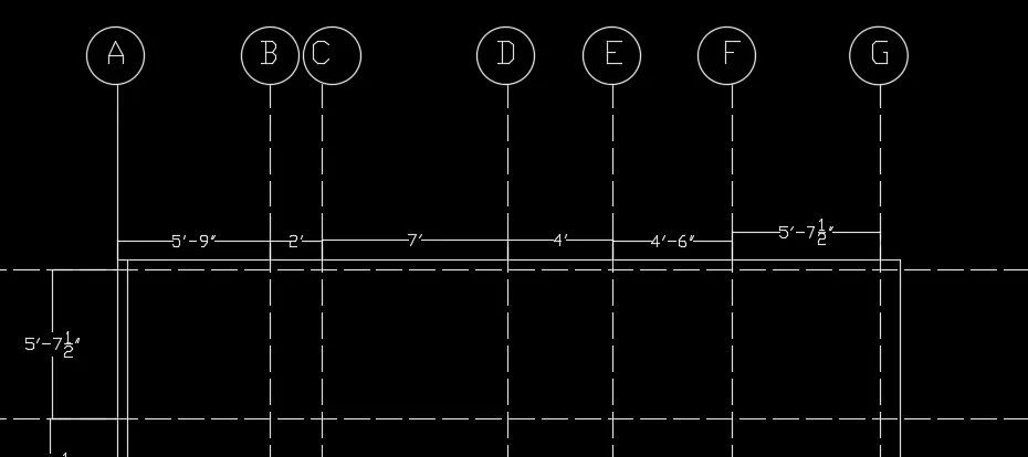
Draw an vertical line with construction line Command "XL-V ".
Offset the vertical line by offset command with offset distance 5'9" ,2'0" ,7'0", 4'0",4'6" , 5'-71/2".
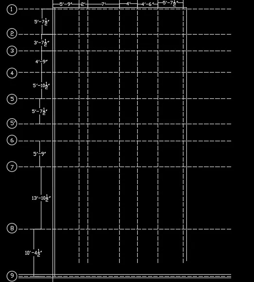
Draw an horizontal line with constrcution line Command "XL-H".
Offset the horizontal lines by offset command with offset distance 5'-71/2" ,3'-71/2" ,4'9" ,5'-101/2",5'-71/2",3'9",5'9", 13'10-1/2",10'41/2".
Change the line type of these lines as ISO dash by clicking on line type and selecting load from the dialogue box and make ISo dash current linetype.
Mark the horizontal lines from 1 to 9
Mark the vertical lines from A to G.
Draw the bottom thickness of wall as 9" with the grid line at the centre.
A thickness of 41/2" is drawn from the grid line inside the left vertical grid line.
Drawing columns:
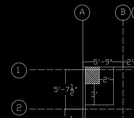
Column between grid line A&B and 1&2. - Column size of 24" x24".
From the 41/2" thickness line draw a rectangle of 24" x24".by "REC" command giving the base point and giving dimensions as 24" and 24" and place the rectangle in the required position.
Explode the rectangle by commnad "EX" .
From the column offset 2' vertically and 3' horizontally
By fillet tool with fillet radius zero join the lines drawn to make the mat.
Hatch the column by command "H" and selecting "ANS 137" and giving scale of 20".
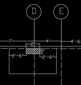
Column between grid line C&E and 1&2. - Column size of 24" x9".
From the grid point D draw an offset of 9-1/2"
Create rectangle by selecting base point as 9-1/2" line and giving dimensions as 24" and 9" .
Delete the 9-1/2" line
Explode the rectangle and give offset with a distance of 2'6" vertical lines on both sides and 3' horizontal line.
Fillet both the corners with fillet radius as zero.
Hatch the columns by command "H" . "ANS137" scale 20".
Column between grid line E&G and 1&2 and F&G and 2&3.- Column sizes 9"x18" and 9" x24".
From the grid point D draw an offset of 4-1/2"
Create rectangle by selecting base point as 9-1/2" line and giving dimensions as 18" and 9" .
Delete the 4-1/2" line
Explode the rectangle and give offset with a distance of 2'6" vertical lines on left side and 2'6" horizontal line.
Fillet left corner with fillet radius as zero.
Hatch the columns by command "H" . "ANS137" scale 20".
For the next column , draw an offset of 4-1/2" upwards the grid line 2
Create rectangle by selecting the 4-1/2" line as base point and dimesion 9" x24".
Explode the rectangle
Offset 2'6" horizontally and vertically from the columns
Fillet the corners with filet radius zero.
Hatch the columns by command "H" ."ANS137" scale 20".
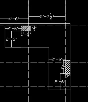
Column between grid line C&E and 2&4 . Column of size 9" x24".
From the grid point 2 draw an offset of 2'10-1/2" .
From grid point D ,offset a distance of 4-1/2"
Create rectangle by selecting base point as intersection of two offseted lines and giving dimensions as 9" and 24" .
Delete the offseted lines.
Explode the rectangle and give offset with a distance of 2'6" on all sides.
Fillet left corner with fillet radius as zero.
Hatch the columns by command "H" . "ANS137" scale 20".
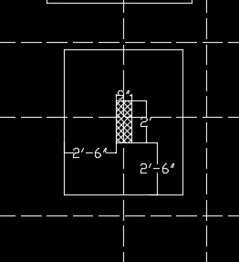
Column between grid line A&D and 1&5 . Column of size 9" x18".
From the grid point A draw an offset of 7'1-1/2" .
From grid point 4 ,offset a distance of 4-1/2".
Create rectangle by selecting base point as intersection of two offseted lines and giving dimensions as 9" and 18" .
Delete the offseted lines.
Explode the rectangle and give offset with a distance of 2'6" on all sides.
Fillet left corner with fillet radius as zero.
Hatch the columns by command "H" . "ANS137" scale 20".
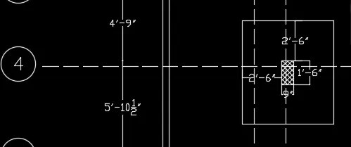
Column between grid line A&B and 4&5' . Column of size 24" x24".
From the grid point 5 draw an offset of 4-1/2" .
Create rectangle by selecting base point as intersection of 4-1/2" and grid line A and giving dimensions as 24" and 24" .
Delete the offseted line.
Explode the rectangle and give offset with a distance of 3' on left and right sides and 2' towards front..
Fillet left corner with fillet radius as zero.
Hatch the columns by command "H" . "ANS137" scale 20".
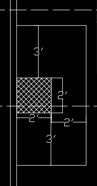
Column between grid line C&E and 4&5' . Column of size 9" x24"
From grid point 5, take offset of 4 1/2" upwards and from gridpoint D ,take 41/2" towards right.
Create rectangle by selecting base point as intersection of 4-1/2" from grid point 5and grid line D and giving dimensions as 9" and 24" .
Delete the offseted line.
Give offset with a distance of 2'6" on all sides
Fillet left corner with fillet radius as zero.
Hatch the columns by command "H" . "ANS137" scale 20".
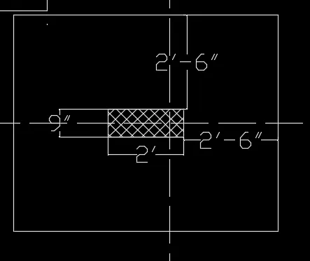
Column between grid line F&G and 4&6 . 2 ColumnS of size 9" x18".
From the grid point 5 draw an offset of 4-1/2"
Create rectangle by selecting base point as intersection of 4-1/2" and wall and giving dimensions as 9" and 18" .
Delete the offseted line.
Explode the rectangle and give offset with a distance of 3' on one sides and 3' towards front..
Fillet left corner with fillet radius as zero.
Hatch the column by command "H" . "ANS137" scale 20".
From the grid point 5' draw an offset of 9"
Create rectangle by selecting base point as intersection of 9" and wall and giving dimensions as 9" and 18" .
Delete the offseted line.
Explode the rectangle and give offset with a distance of 3' on one sides and 3' towards front..
Fillet left corner with fillet radius as zero.
Hatch the column by command "H" . "ANS137" scale 20".
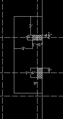
Column between grid line F&G and 6&8 . Column of size 24" x9".
From the grid point 7 draw an offset of 10-1/2" .
Create rectangle by selecting base point as intersection of 10-1/2" and wall and giving dimensions as 9" and 24" .
Delete the offseted line.
Explode the rectangle and give offset with a distance of 3' on left and right sides and 3' towards front..
Fillet left corner with fillet radius as zero.
Hatch the columns by command "H" . "ANS137" scale 20".
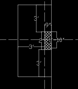
Column between grid line D&Fand 6&8 . Column of size 24" x9".
From the grid point 7 draw an offset of 10-1/2" and from gridpoint E take an offset of 4-1/2".
Create rectangle by selecting base point as intersection of 10-1/2" and 4-1/2" and giving dimensions as 24" and 9" .
Delete the offseted line.
Give offset with a distance of 2'6".
Hatch the columns by command "H" . "ANS137" scale 20".
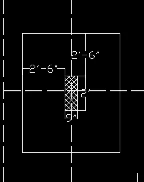
Column between grid line A&Dand 5&8 . Column of size 24" x9" and 24" x24".
From the grid point 6 draw an offset of 4-1/2" downwards .
Create rectangle by selecting base point as intersection of 4-1/2" and wall and giving dimensions as 24" and 24" .
Delete the offseted line.
Draw a 9" thickness wall from the column at a distance of 3'9".
From the corner draw another column by rectangle 9" x2'.
Draw the wall downwards at a distance of 5'8-1/4" and rightwards 2'4-1/2".
Draw another column of 9" x2' on the rightmost side.
Mirror the 24" x24" column on the other side ,with mirror line the midpoint between grid 6&7.
Give offset with a distance of 2'6" to the front from the wall and column
Give offset distance of 3' to the right and left side.
Hatch the columns by command "H" . "ANS137" scale 20".
Hatch the wall by "AR CONC " scale 1.
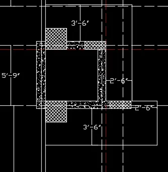
Columns between grid line A&Dand 5&8 . Column of size 24" X24" and 9"x2'6".
From the grid point 8 draw an offset of 9" downwards .
Create rectangle by selecting base point as intersection of 9" and wall and giving dimensions as 24" and 24" .
Delete the offseted line.
Explode the rectangle and extend the base of rectangle and from grid point C offset 4-1/2" and create a rectangle of 9" x 2'6".
Give offset with a distance of 2'6" to the front and left of the 9"x2'6" and offset of 3' from the 2'x2' rectangle..
Hatch the columns by command "H" . "ANS137" scale 20".
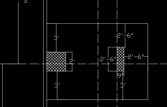
Column between grid line F&Gand 8&9 . Column of size 3' x9".
From the grid point 8 draw an offset of 4-1/2" downwards
Create rectangle by selecting base point as intersection of 4-1/2" and wall and giving dimensions as 3' and 9" .
Delete the offseted line.
Give offset with a distance of 3'.
Hatch the columns by command "H" . "ANS137" scale 20".
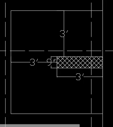
Text and dimensioning:
Text are done by multiline text with height 10" .
Dimensions is done by dimension tool in toolbar and measure all the distances between the grid lines and other required distances.
Creating layers:
Layers are created by clicking on layer properties and layer manger dialogue box apperas.
Layers are created for gridline,columns ,dimensions,walls ,mats.
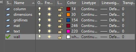
RESULT: The raft layout is drawn.
CONCLUSION:
The cabinet , floor plan , kitchen layout ,column details and raft layout are drawn using Auto Cad.