Week 6 Challenge
Aim and introduction – Ultimate aim is to construct a feasible, sustainable, cost-effective underpass by analyzing and designing raft foundation considering different loads, such as dead load (self weight), superimposed dead load, earth pressure, live load surcharge, breaking load, temperature and live load etc.
In this challenge we will study for the bending moment, shear force and deflection diagrams for the raft foundation in STAAD compare them with manual calculation for following set of loads. There is fill of 1m on top slab.
- Earth Pressure
- Self weight
- Surcharge
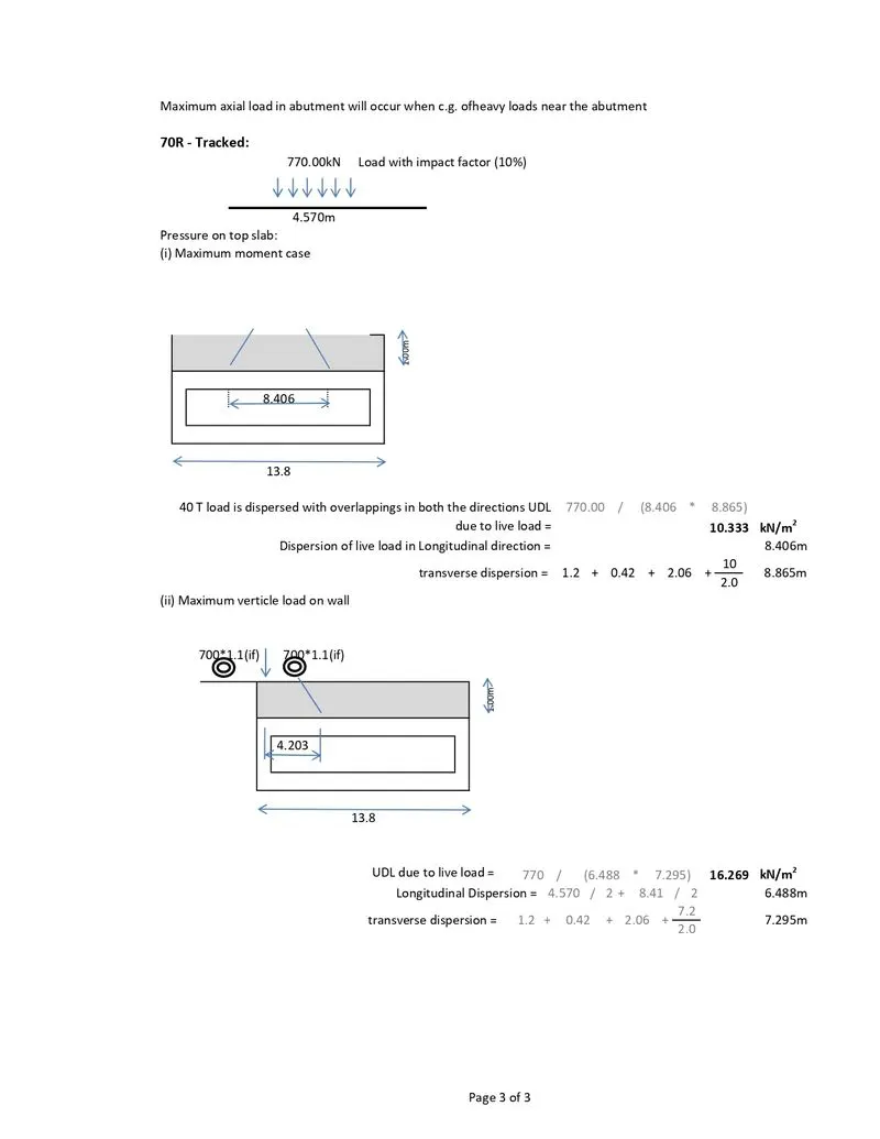
- 70R load
The design of various components of the bridge, in general are based on provisions of IRC. The list of IRC Codes (latest revisions) given below will serve as a guide for the design of structures.
IRC : 5 - 2015 Standard Specifications and Code of practice for Road Bridges, Section I - General Features of Design
IRC : 6 - 2014 Standard Specifications and code of Practice for Road Bridges, Section II - Loads and Stresses
IRC : 112 - 2011 Code of Practice for Concrete Road Bridges
Step 1) Creating a model in STAAD
The bridge under pass is modeled as a frame structure taking the centre line dimension.
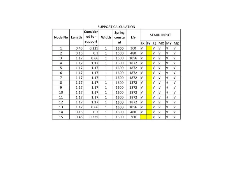
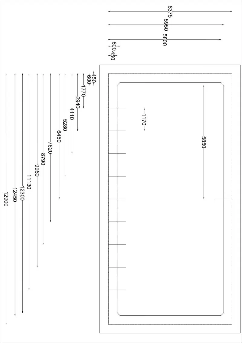 Bottom slab devided in 10 devision. Spring supports are provided to following points.
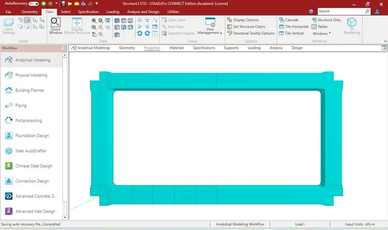
STAAD PRO MODEL
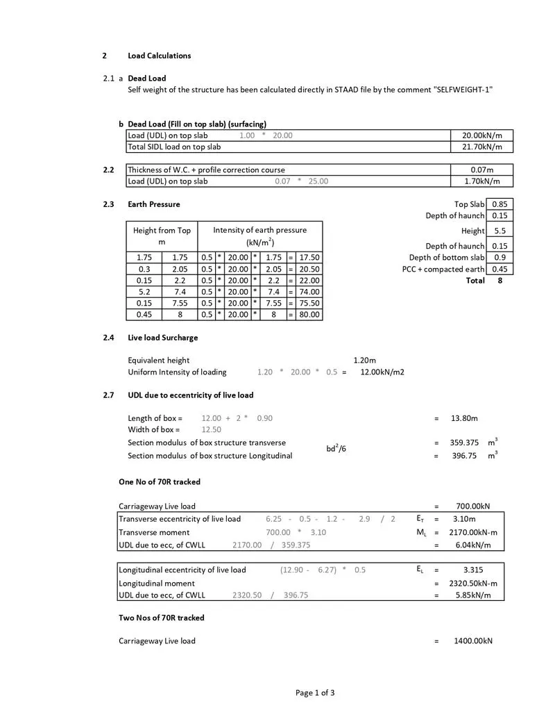
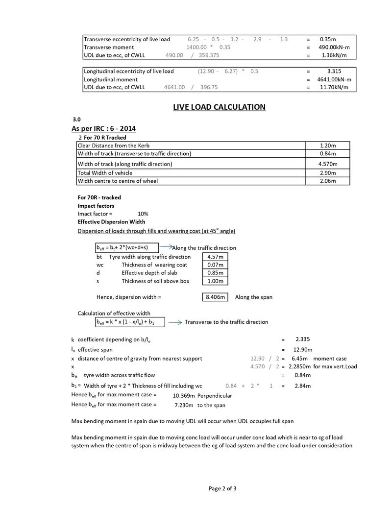
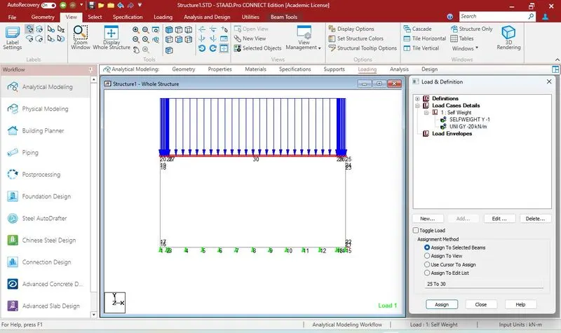
 Applying dead load on structure
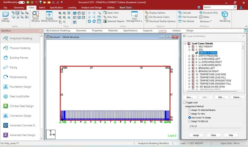
 SIDL (65mm wearing coat) on bottom slab
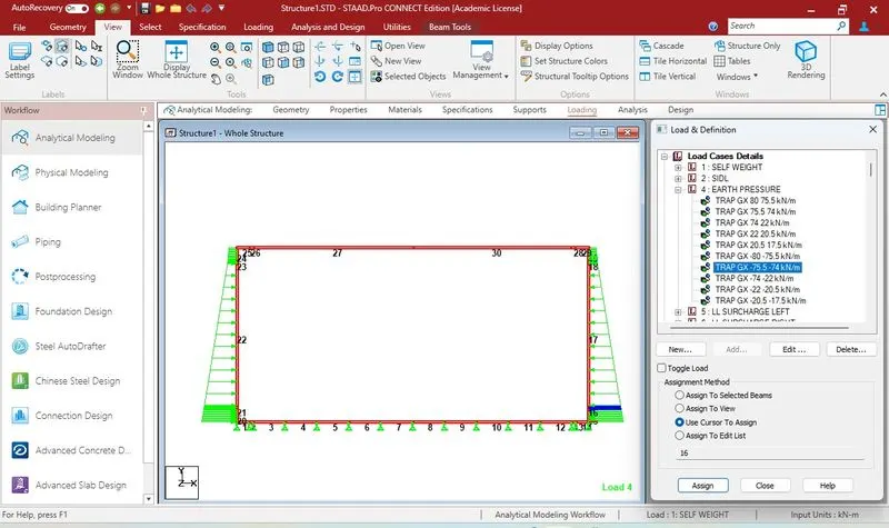
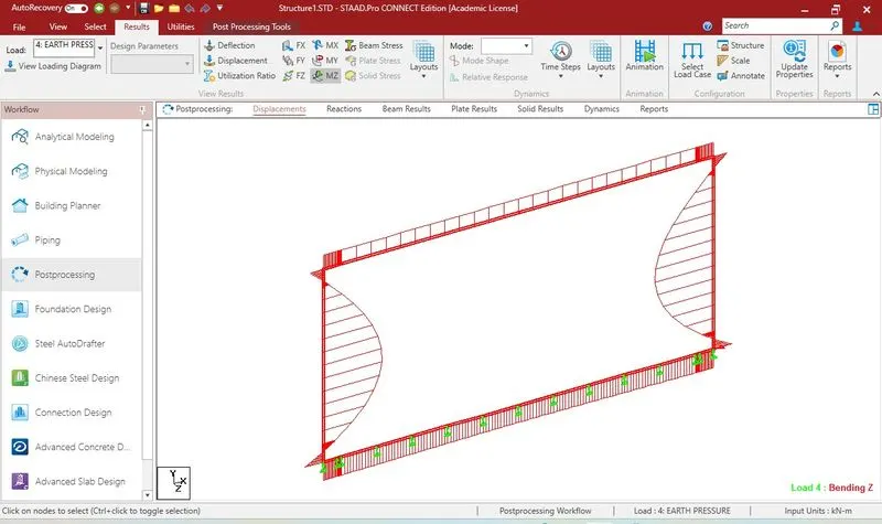
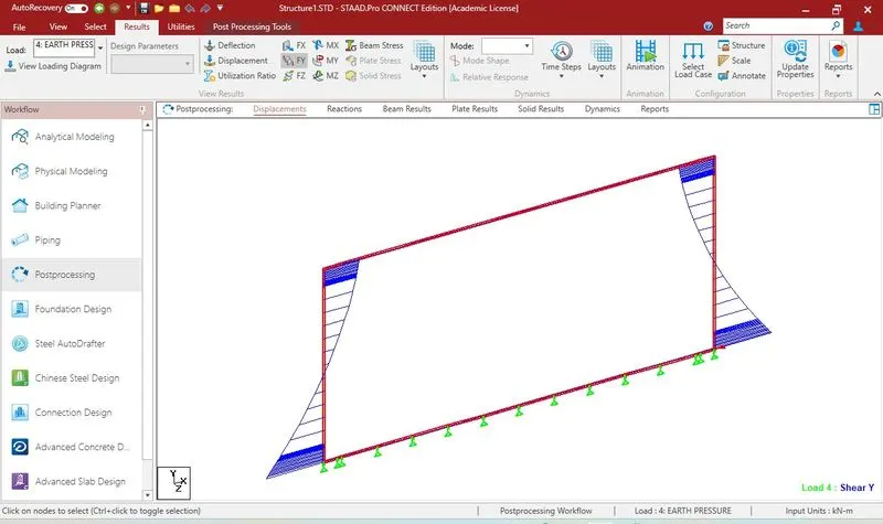
 Earth pressure
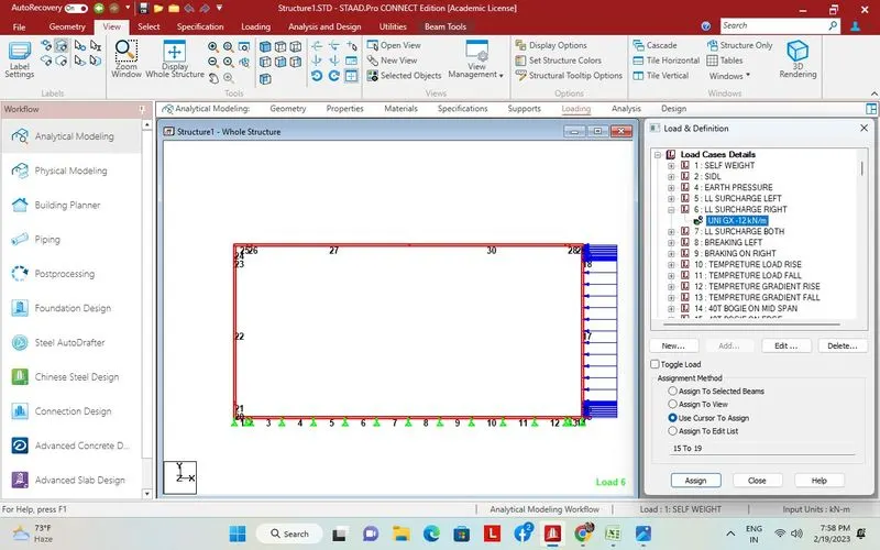 70R Tracked on mid span
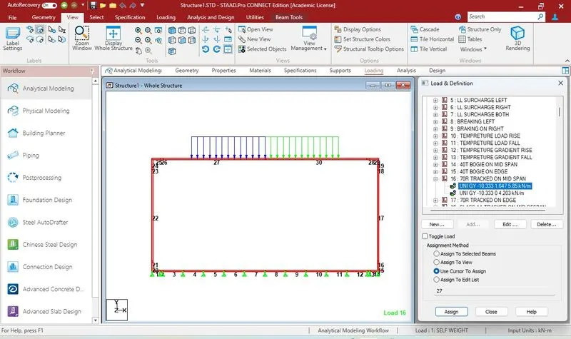 170R on edge
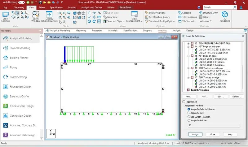 Partial safety factors for verification of structural strength (ULS) are considered as per Table 3.2 of IRC:6 - 2014.
The anaysis is carried out using staad pro and a critical case from analysis result adopted for design.
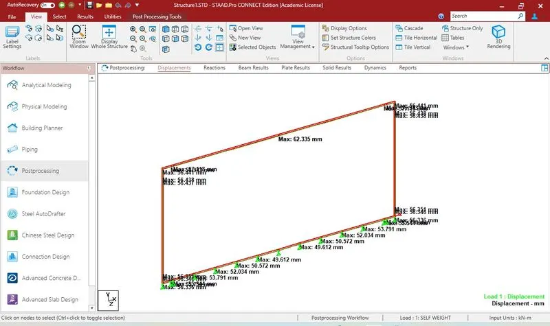
Dead Load Bending moment
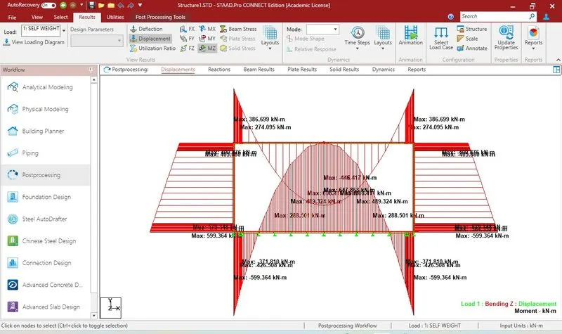
Shear force
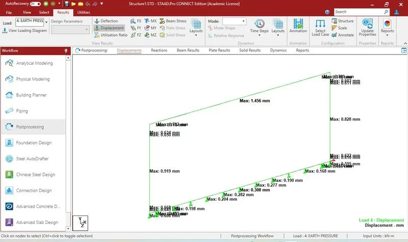
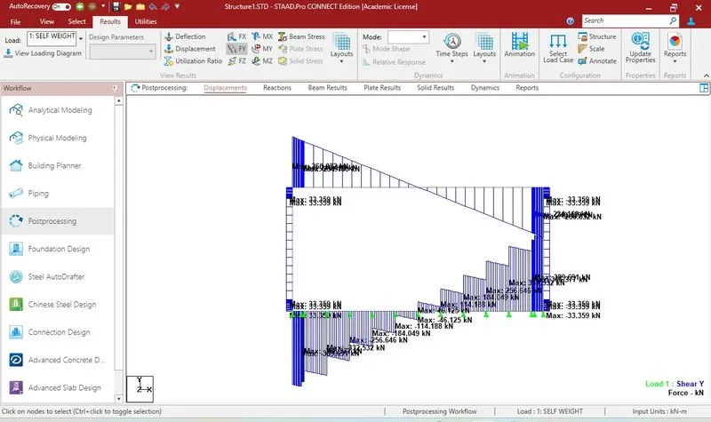 Displacement
 BM for earth pressure
 Shear
Shear
 Displacement
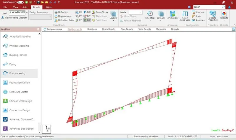
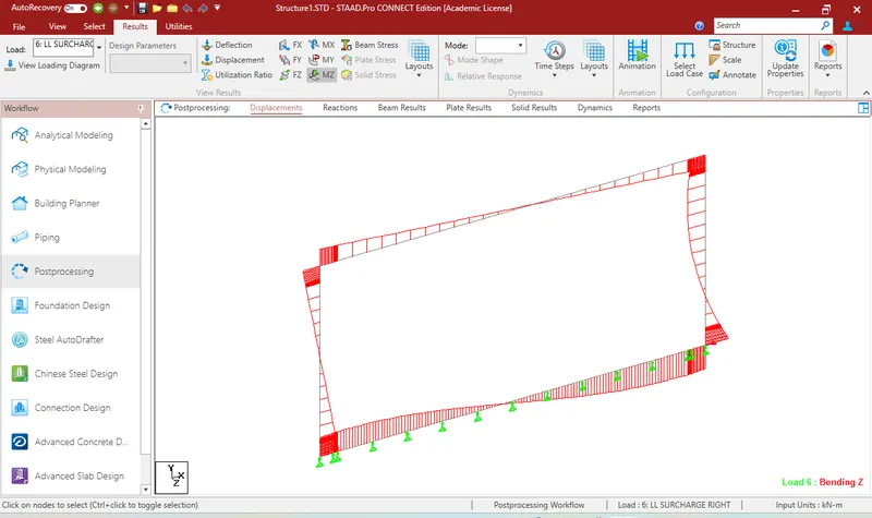
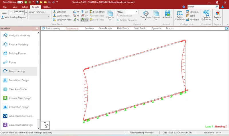
 LIVE LOAD SURCHARGE
Left BM
 rIGHT
rIGHT
 bBM both side
 1Shear for Both side LL surcharge
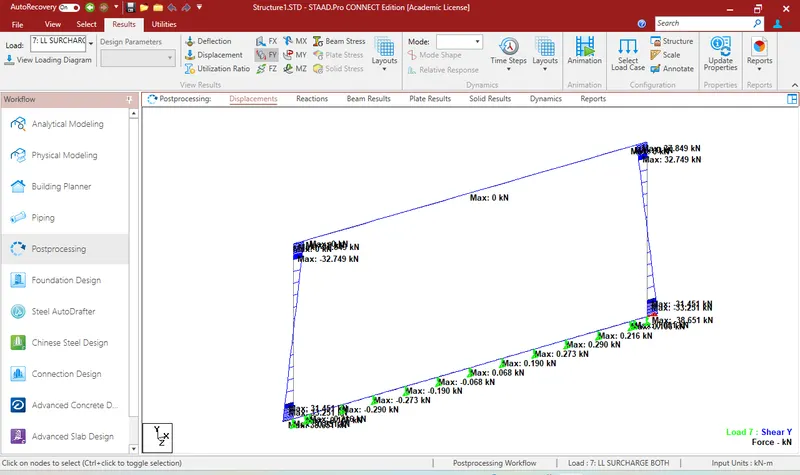 BM diagrame for 70R tracked vehicle on mid span
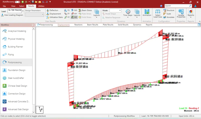 Shear force for 70R Tracked on edge
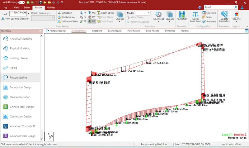 Shear diagramme
 Q2 Design of the member based the analysis
Dimensions of the section are already given. Tempreture load assumed. live load of 40T Bogie and Class AA also considered.
Provision of reinforcement and checking adequacy of streses in the concrete and reinforcing steel is the task or challange.
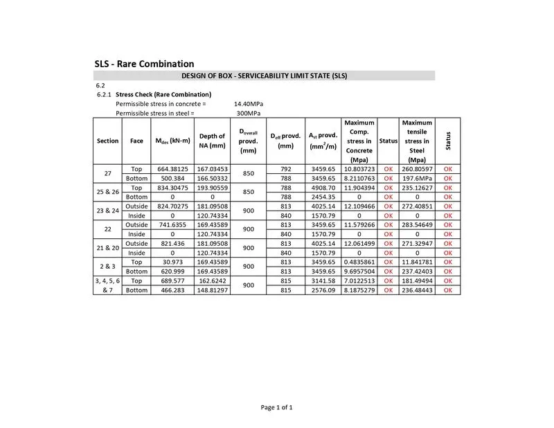
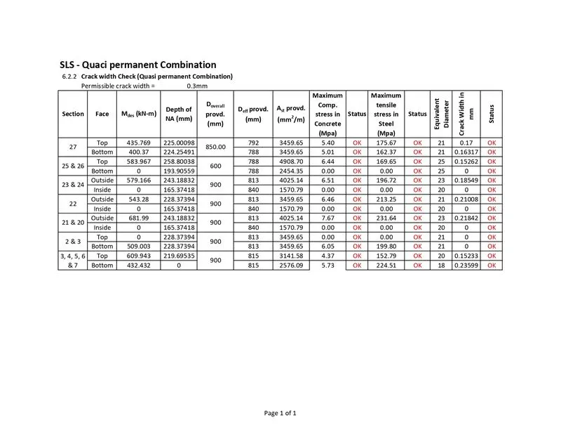
For this Bending moment and shear force envelopes are obtained by using ULS, SLS Rare, SLS RARE WITH TEMPRETURE ACCOMPANING, SLS RARE WITH TEMPRETURE LEADING, SLS QUASI PERMANENT, SLS QUASI PERMANENT WITH TEMP ACCOMP., SLS QUASI PERMANENT WITH TEMP LEADING with partial factor. Live load combination separately applied separately without partial factor.
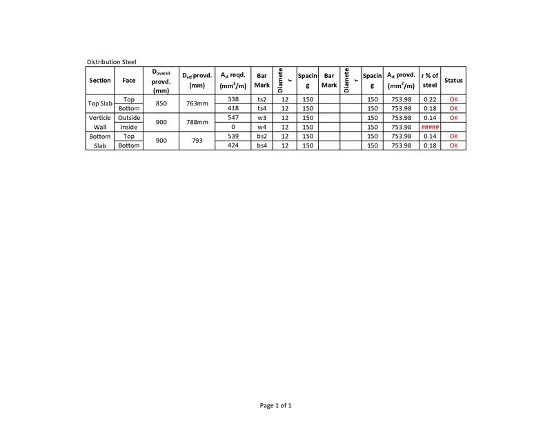
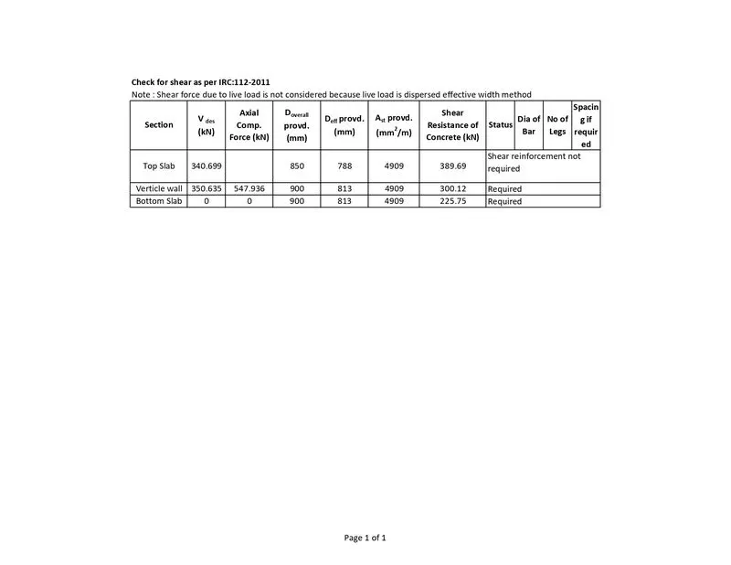
Following summary chart are for different members for corresponding CRITICAL bending moment and shear force obtained.
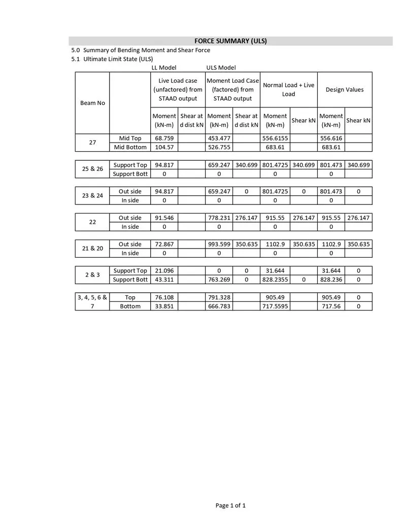
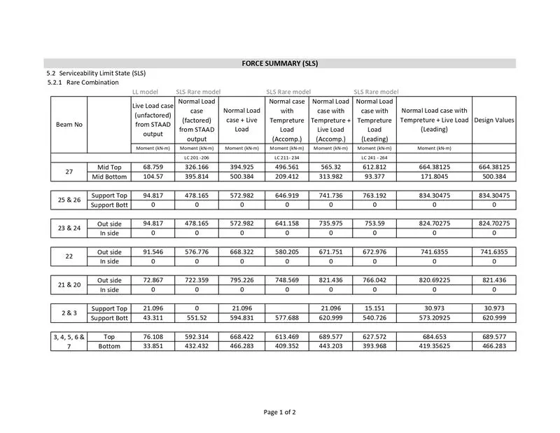
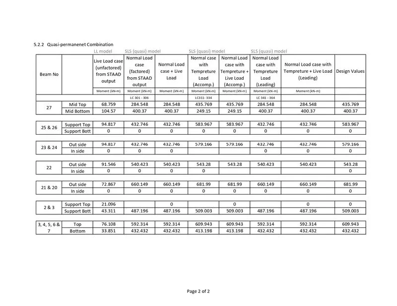 Check % of steel
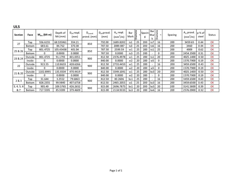
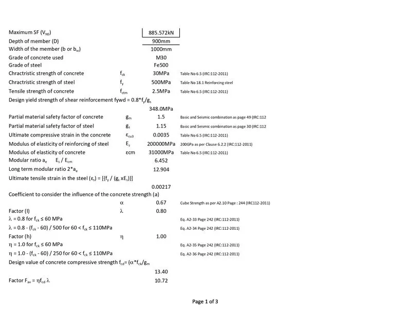
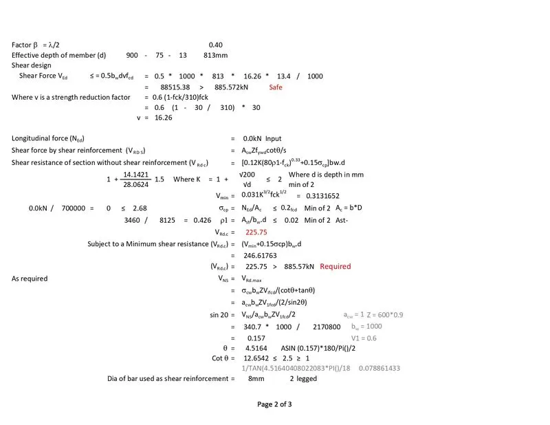
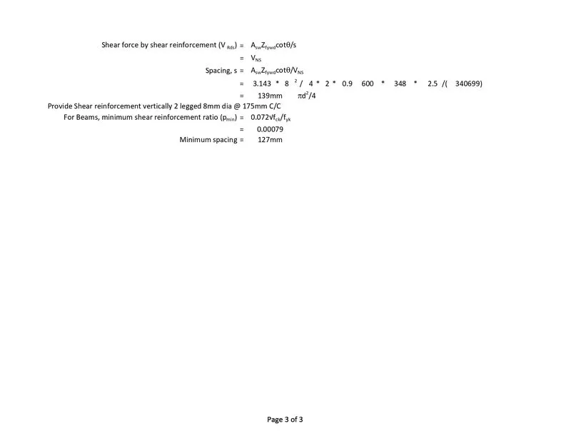
 Check for shear
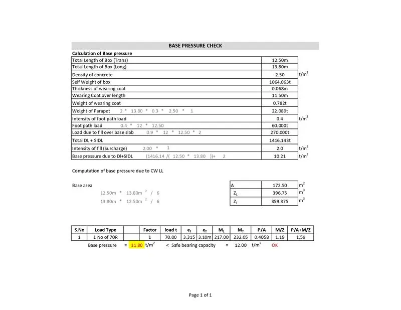
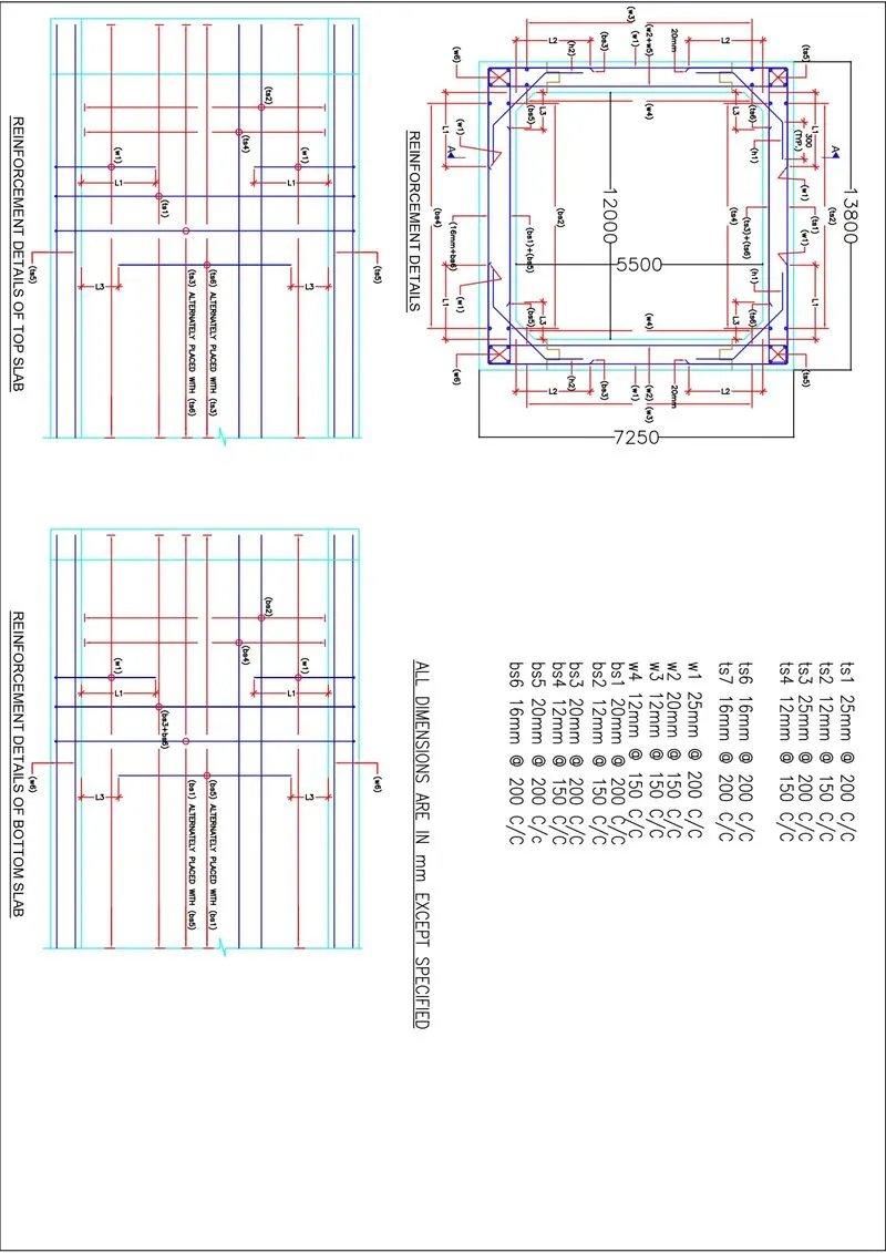
Q 3 Reinforcement detailing
Q 4 Change in shear earth fill 5m
Dead Load (Fill on top slab) (surfacing)
Load (UDL) on top slab 5m X 20kN/m3 = 100kN/m
Thickness of W.C. + profile correction course = 68mm
Load (UDL) on top slab 68 X 25 /1000 = 1.7kN/m
Total SIDL load on top slab = 101.7kN/m
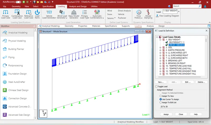
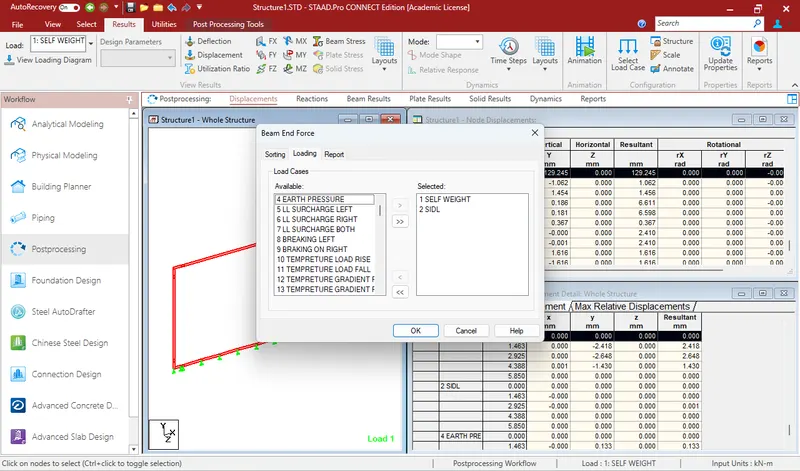 After analysing the design shear force is taken
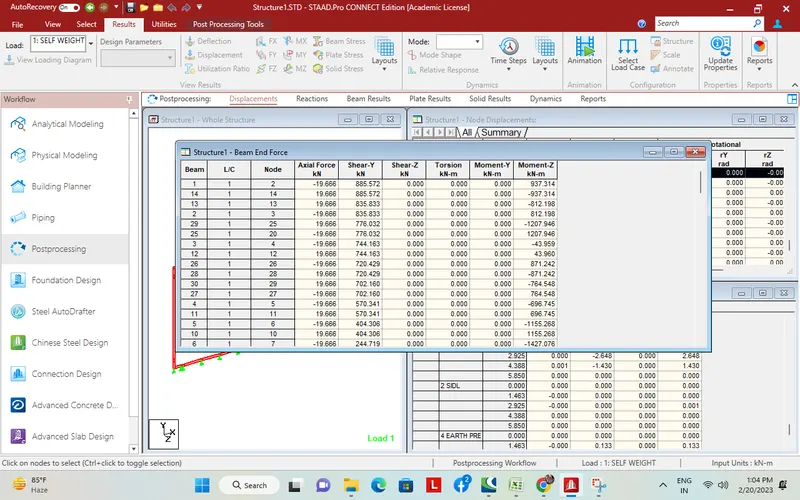 885.572kN