Week 6 Challenge
1. Create a MicroStation rectangle, complex line and apply civil rule features to the same with linear > matchline feature definition.
2. Build geometry of your own parameters with geometry builder tool.
3. *Design an alignment on the 1st intersecting street. Design the proposed profile for the same. Name the alignment as “INT_01” and “PGL_INT_01”. Assign stationing starting from start of the alignment with 50+00.
4. *Design the roadway layout for this intersecting street till the survey/topo limits. Use above alignment as a starting point. Refer to the parameters from week 5 challenge # 01, 02. Create driveway and intersection openings referring to the background imagery.
(* Use best practices. Check snaps. Check tie-in conditions in plan and profile to existing conditions. Use proper feature definitions. Use appropriate geometry)
1. Create a MicroStation rectangle, complex line and apply civil rule features to the same with linear > matchline feature definition.
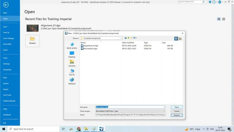
- Create new file of 2seed file, name as microstation save it in a proper folder click on save
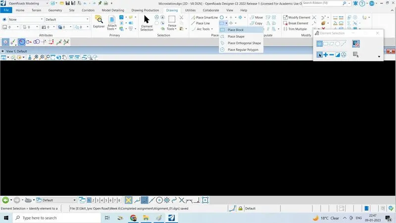
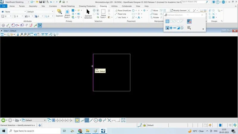
- Go to Drawing tab in placement session click on place line and draw a rectangle
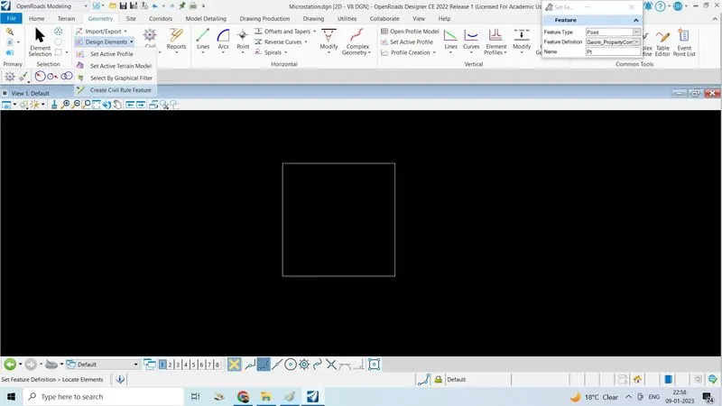
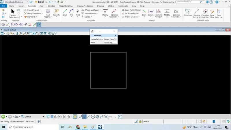
- Go to gemetry tab click on design elements click on create civil rule features add feature definition geo-temp
- Microstaion rectnagle is created civil rule feature is apply
- Go to geometry tab click on line draw two or 3 tangent lines click on line between two points set feature definitions
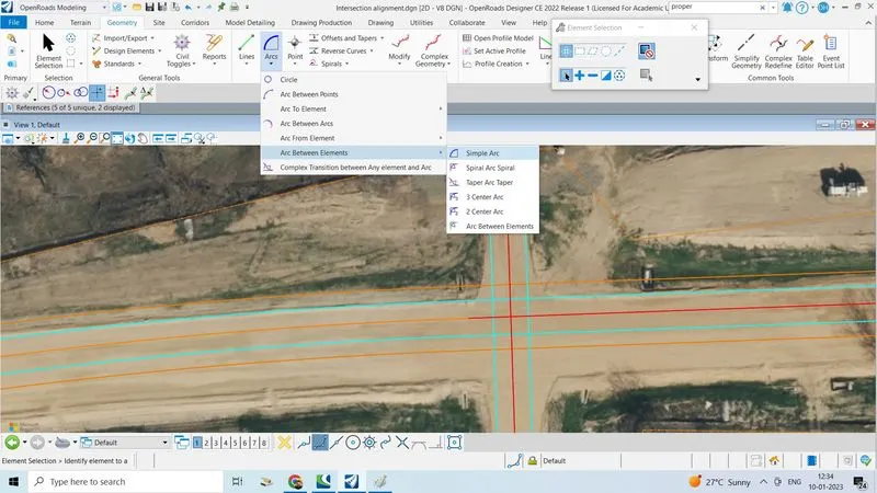
- Click on arc select simple arc locate 1st element and 2nd element give the radious and click enter
- Click on complex click on complex by element to join the lines
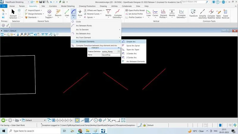
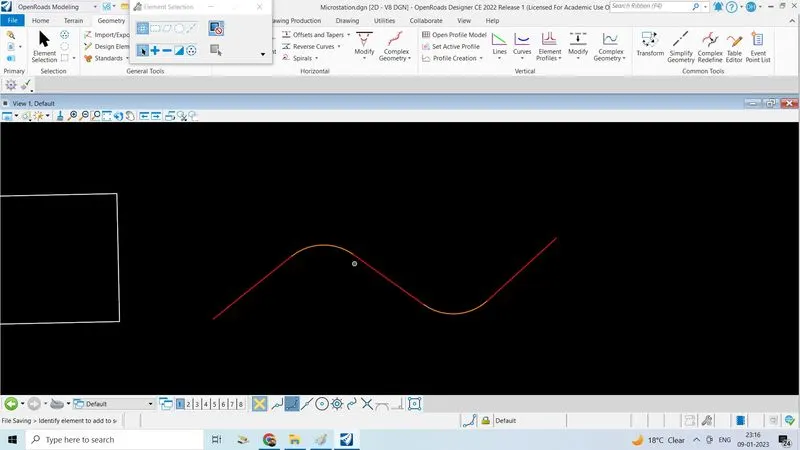
2. Build geometry of your own parameters with geometry builder tool.
- Create new file 2seed of name geometry builder click on save
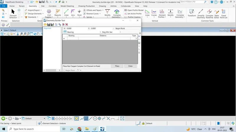
- Go to geometry builder, click on complex geometry click on geometry builder
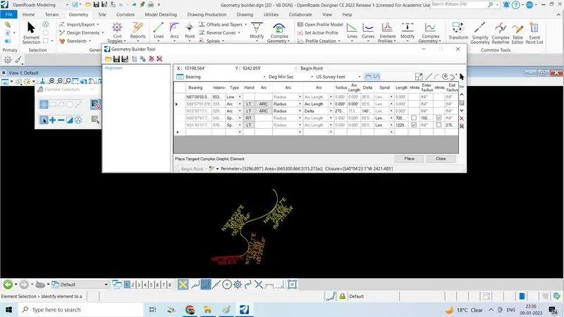
- Click on add new geometry give name as alignment
- Click on insert line and draw a line of same lenght
- Click on arc and draw an arc after drawing we can change of lenght and radii
- After we can change line into arc, spiral the geometry is builded with any own parameter
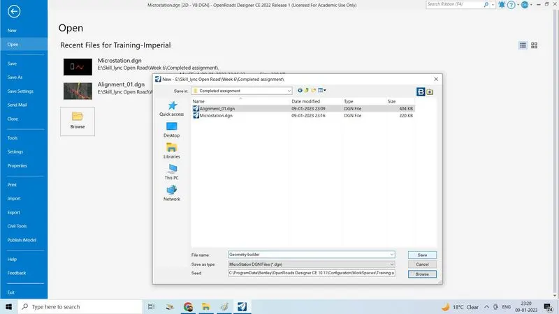
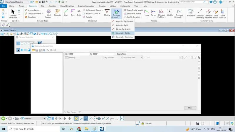
3. *Design an alignment on the 1st intersecting street. Design the proposed profile for the same. Name the alignment as “INT_01” and “PGL_INT_01”. Assign stationing starting from start of the alignment with 50+00.
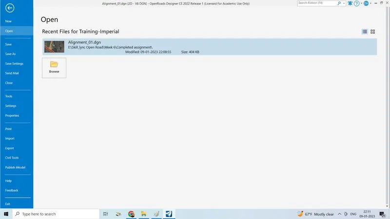
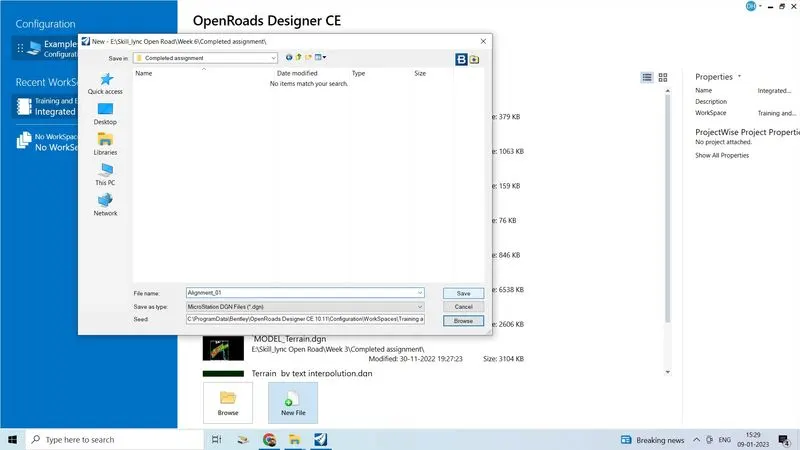
- Create a new file with 2D seed name as alignment_1 save it in a proper folder click on save
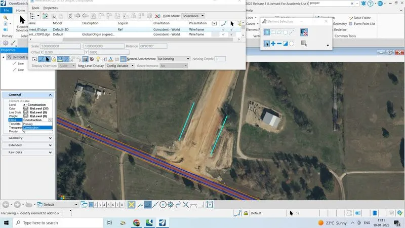
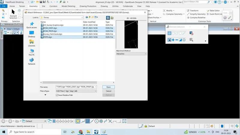
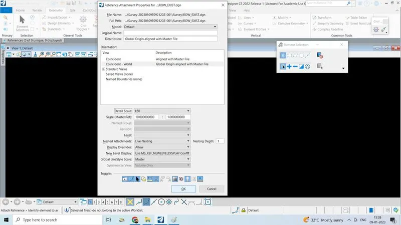
- Attach the right of way existing dgn and right way praposed dgn and topo Dgn as interactive method click on open
- Select model as default click on coincident world
- Select live nesting and nesting depth 1
- Select detail scale 1:50
- Click on fit view to view
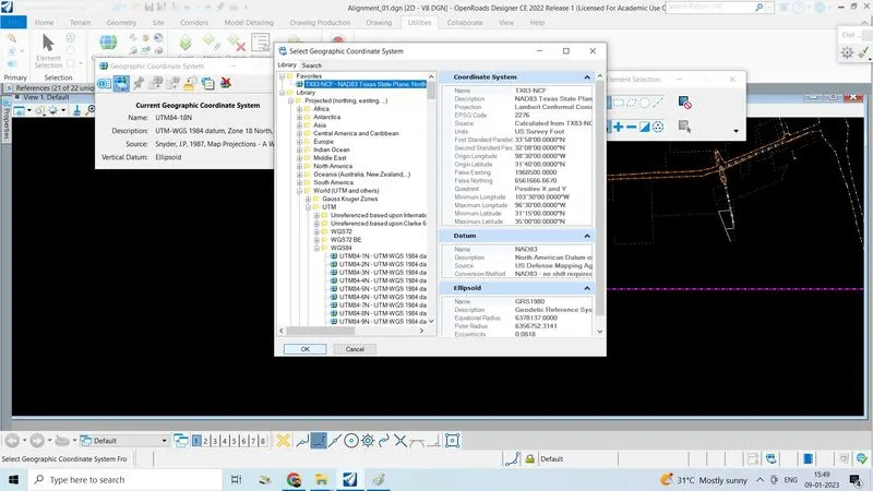
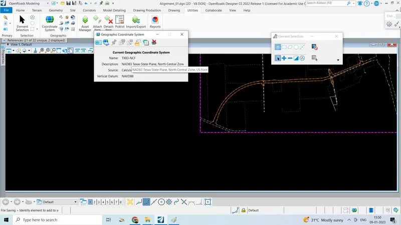
- Set the co-ordinate system, go to utilities tab ,click on co-ordinate system, co-ordinates as TX83-NCF-NAD83 Click on ok
- Click o view attributes, goto background map select type as aerial
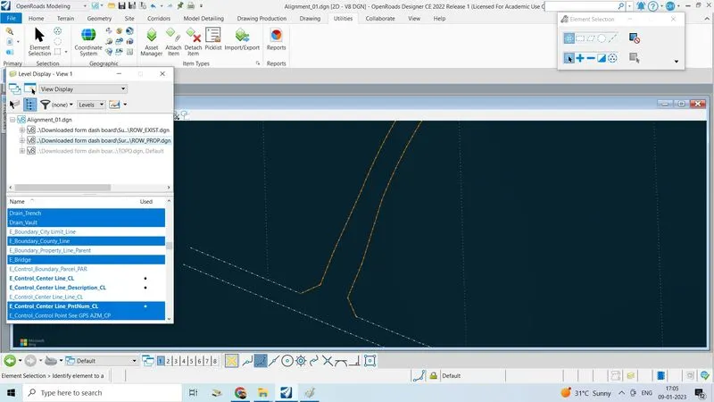
- Hide the unnessary layer as fallows
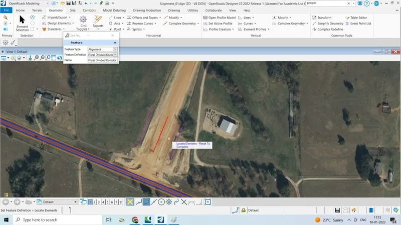
- Go to geometry tab and click on lines, click on select line between points set the feature definition and design the alignment
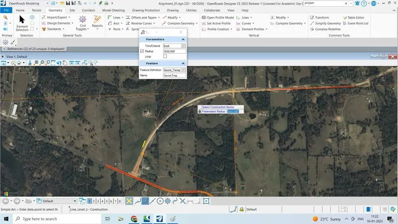
- Click on the arc and click on arc between elements-->simple arc. set the feature definition
- Locate first entity and second entity give the radius click enter the line is joined
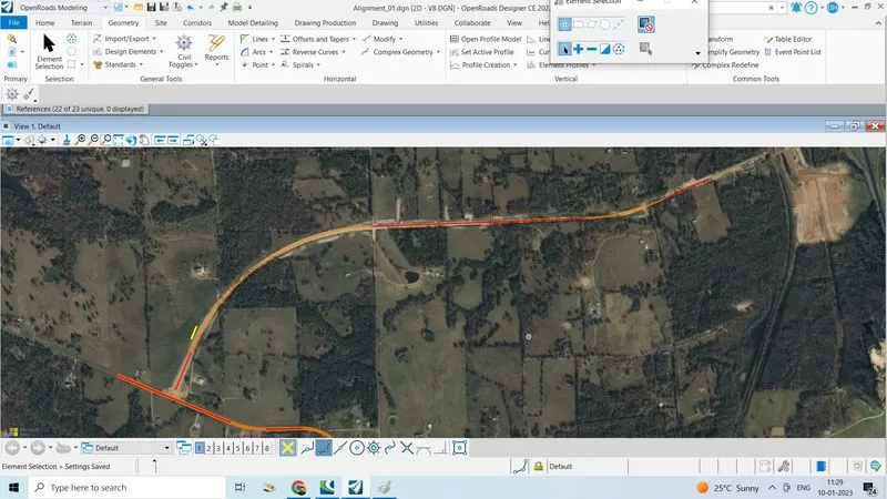
- Click on complex geometry--> click on complex by element to complex the alignment
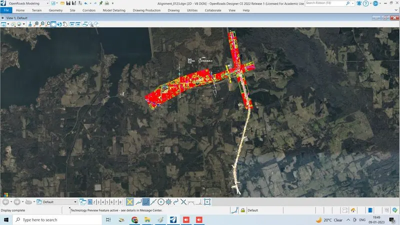
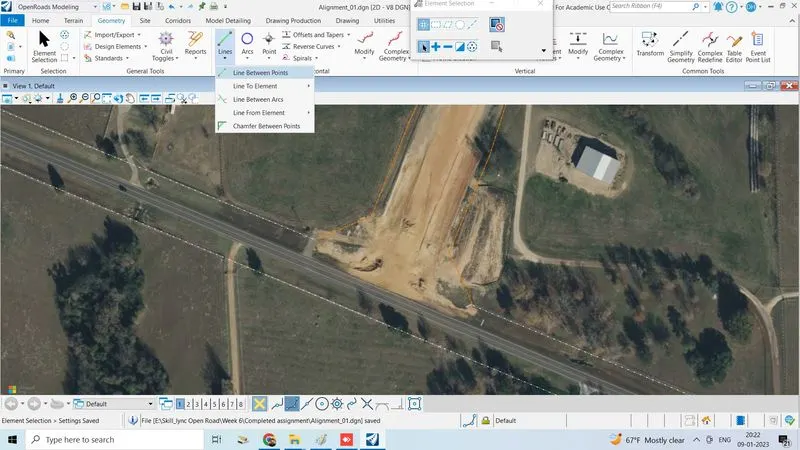
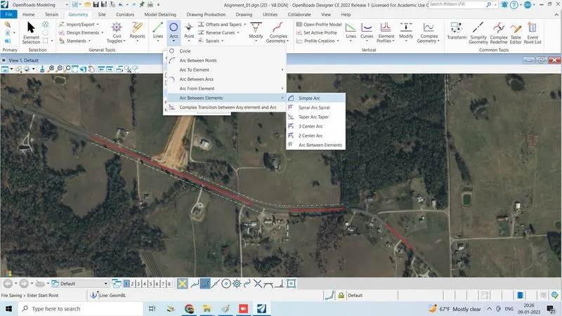
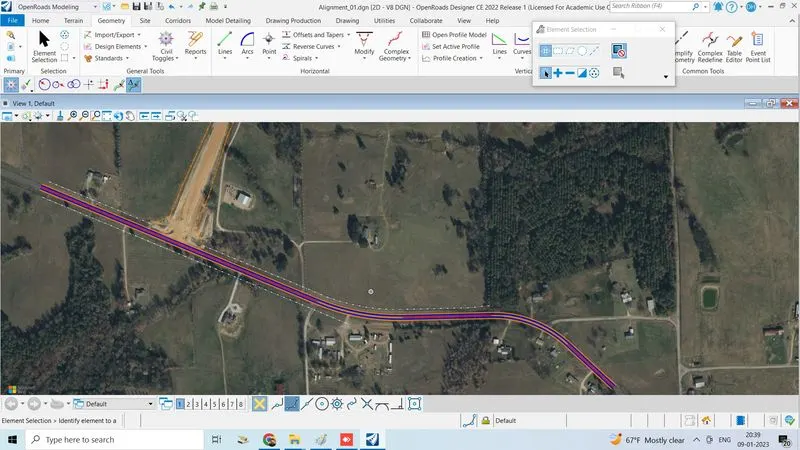
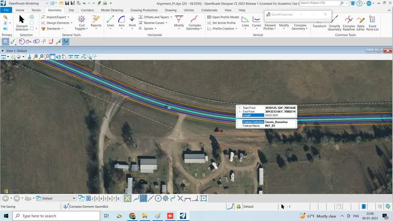
4. *Design the roadway layout for this intersecting street till the survey/topo limits. Use above alignment as a starting point. Refer to the parameters from week 5 challenge # 01, 02. Create driveway and intersection openings referring to the background imagery.
- open the previous(same file)
- Turn off all the layers and turn only background map
- Copy the element and keep it same point by operating space key and turn of the prop ROW for same time
- Select that two small element go to properties convery class primary to construction and level as Z-Construction which will help to print the element
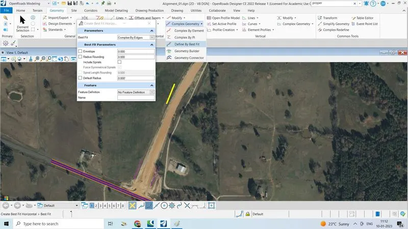
- Now go complex geometry select best fit, Select best fit as complex by edgest, now locate primary edge element and secondary edge element no spiral
- Select the line go to properties convert to horizontal rule once it converted it will have the civil rule
- And now delete that copied element and turn on the topo ROW
- Do the same procedure for curve portion select simple arc and Locate 1st entity 2nd entity give radius that is alignment is done
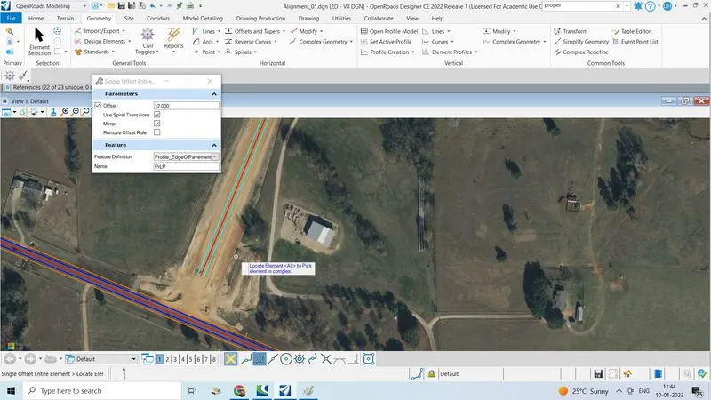
- Now give offset for entire element so click on single offset entire element and give the offset distance 12 feet and feature definition
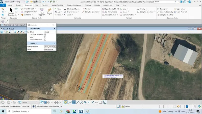
- Same as add the shoulder 10 feet and give correct feature definition
- Let us create the intersection junction, let turn on the top file drawline with respect to a topo straight line
- Give lane width offset set the feature deffinition
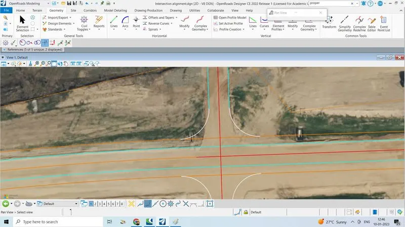
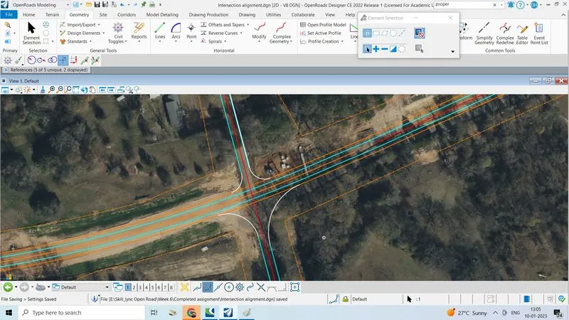
- Click on arc click on simple arc locate 1st entity and 2nd entity the radius now intersection junction is created
- Do the same procedure for all the intersection point