Project 2
1. Complete a project based upon all previous lectures.
2. See completed .PDF as a go-by for project criteria.
1. Complete a project based upon all previous lectures.
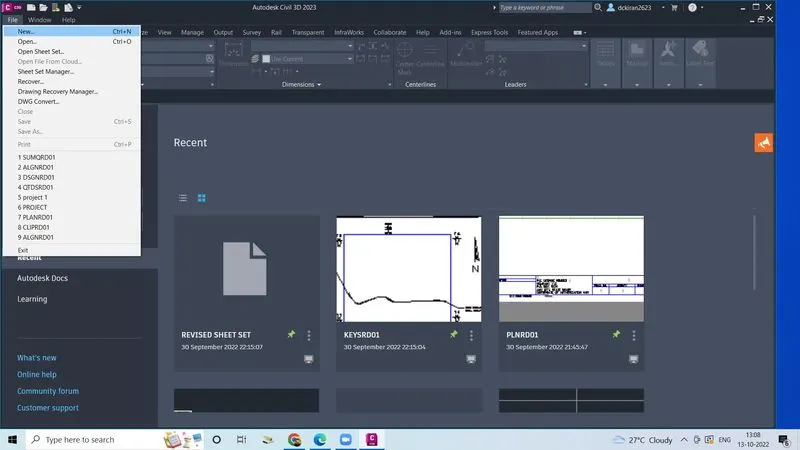
- go to file
- Click on the new
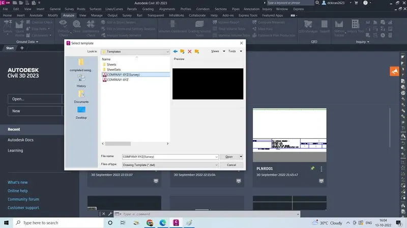
- Select one template file which provided by the company (skill-lync/downloaded from dashboard/support/template/company xyz(survey))
- Click open
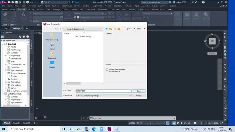
- Type command CTRL+S give name as (SURVRD03) as a .dwg form and save in a proper folder skill-lync/week7/completed assignment
- Click on the save, now file is created
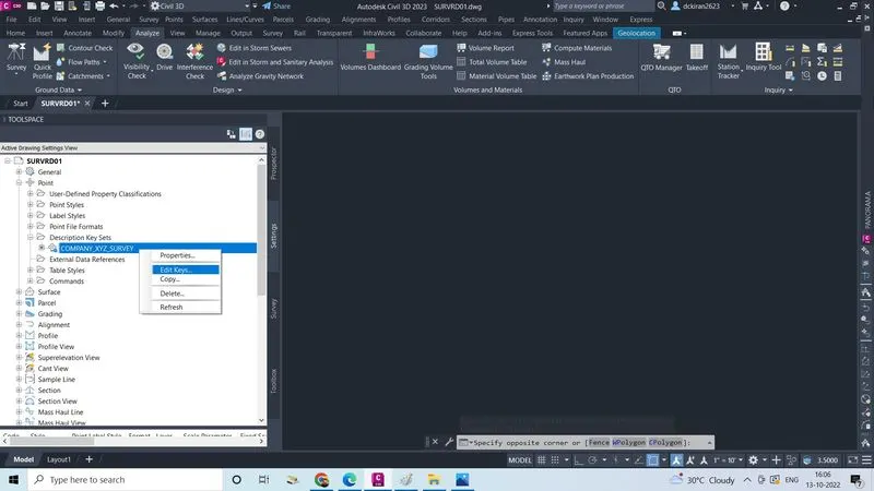
- In the SURVRD03, go to toolspace/setting
- Click on the points/description key sets,select and right click on the civil3D,Click on the edit key or click on the points/description key sets, select and right click on the civil3d,click on the properties give name and description key sets and
- Select and right click on description key set click on edit key
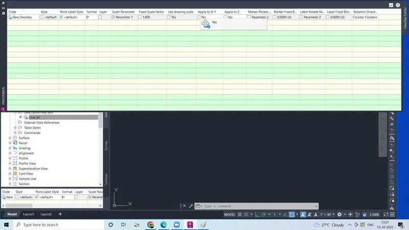
- PANORAMA table will open in that enter or import all the code,style,points lable style,formate,layer,scaleparameter,fixed scale factor,use drawing scale,apply to X-Y,...etc as provided by company
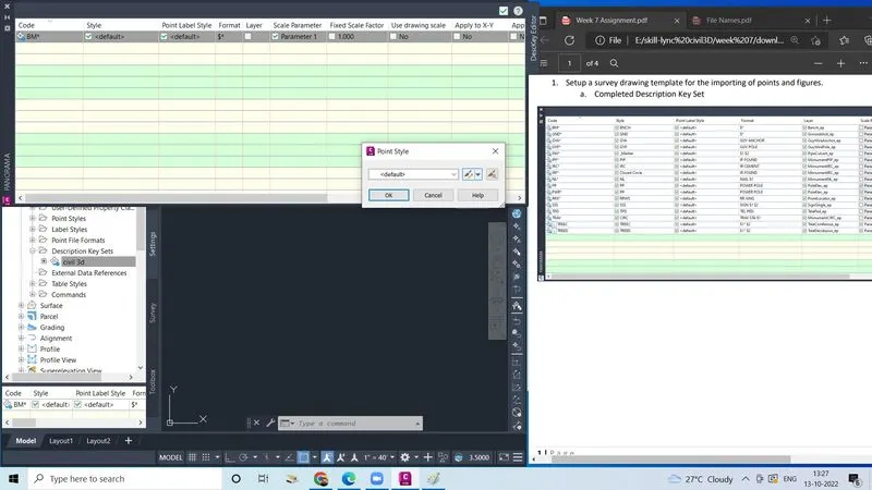
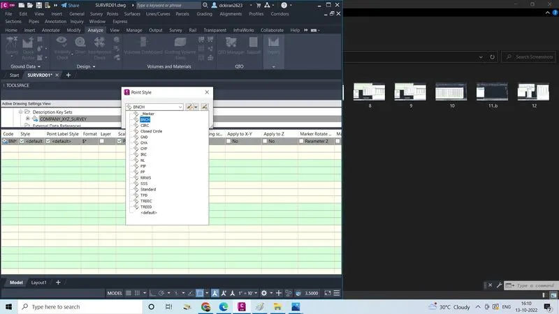
- 1st enter the code as BM*,next click on style defualt there create new point style, if it is not exist
- Give the name as BNCH as per the company click apply and ok,ok
- Click on formate is not exist create new layer as per company
- If layer is not exist create new layer as per company
- If scale parameter is unchecked then make check as per company
- And same thing to every one
- Repeate the same procedure for each and everything
- Now description key set is ready now
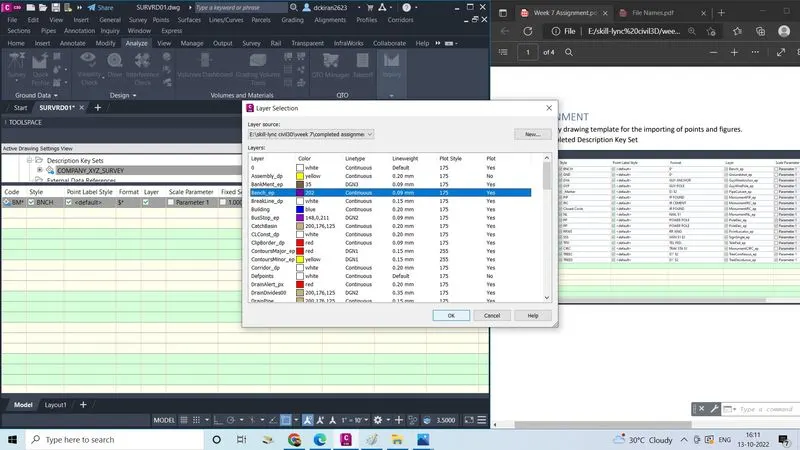
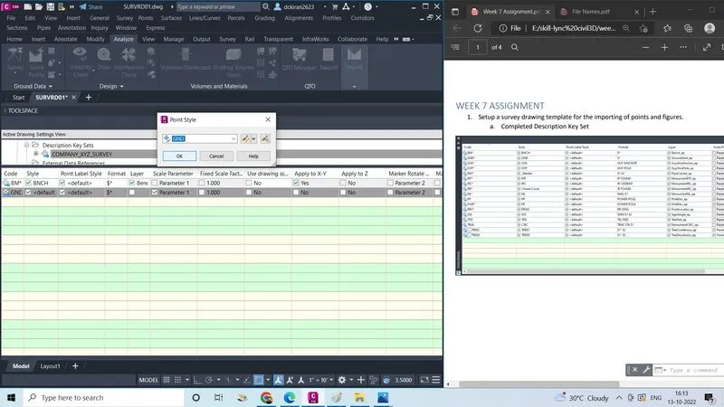
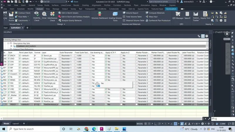
- After importing all the discription keys
- Now in the (SURVRD03) file go to toolspace/survey Click on the figure prefix database
- Select and right click on the sample
- Click on the manage figure prefix database
- Figure prefix database manger sample dailog box will open, in that
- Click on (+) mark and import all
- The figure prefix database as per the company provided
- And click ok
- Now every figure prefix database is imported
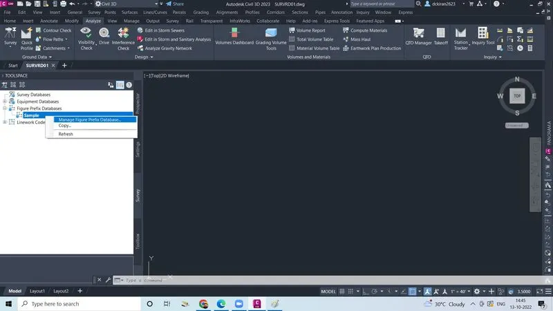
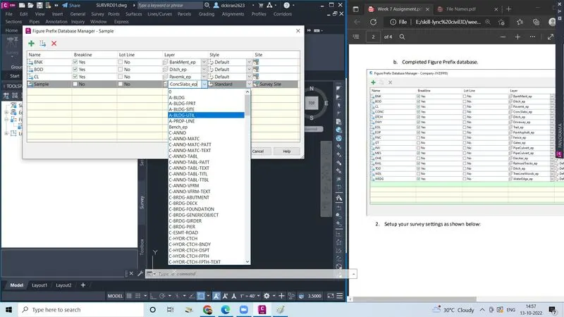
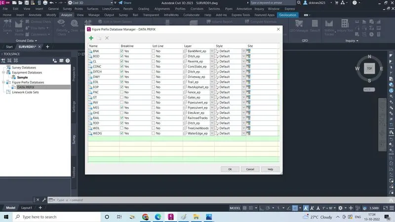
- After importing all the points and figure (discription key sets and figure prefix database)
- Now in (SURVRD03) file/toolspace/survey
- One surveying tripod mark is there,click on there one survey user setting dailogbox will open
- All the survey data as per the company provided but store every path in the (skil-lync/week7/completed assignment)
- Select colour,select layer, if it not exist create layer
- Click ok
- Survey setting is over (setup)
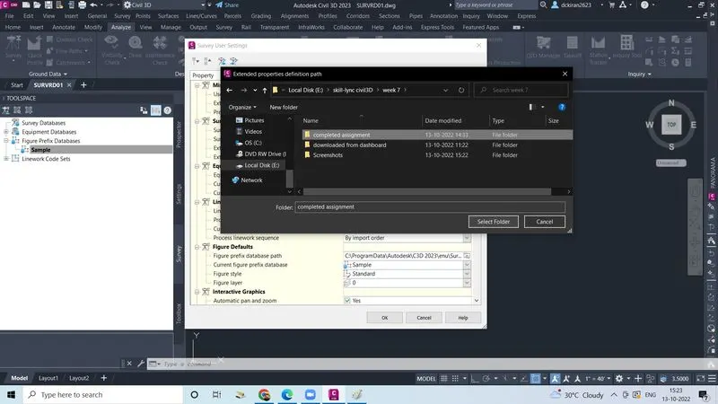
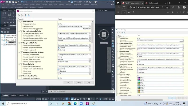
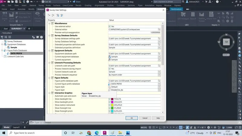
- After setting up the survey
- Select and right click on the line work code sets
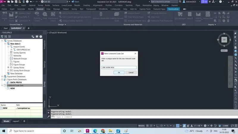
- Click on the "New"
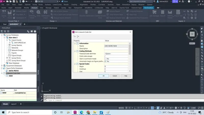
- Give the line name "Line work new" click on ok
- Line work code set will open
- Click ok after
- In SURVRD03/toolspace/Survey, select and right click on the survey database, click on new local survey database
- Small naming box will open, their give the name of the folder as "New database"to create the new survey, data base
- And click ok
- Now select and right click on the new
- Now Click on the new data base /and select and right click on the import survey data
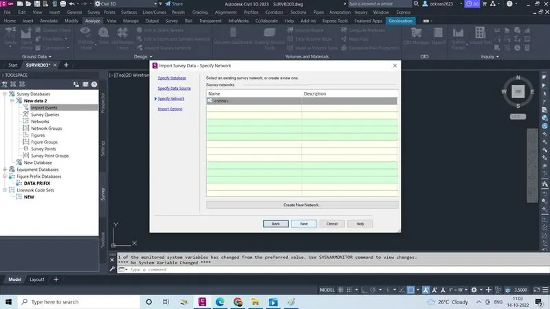
- Click on the new database and click next
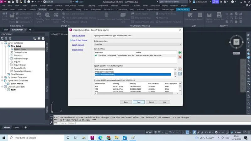
- In specify data source option,select the data source type as "point file"
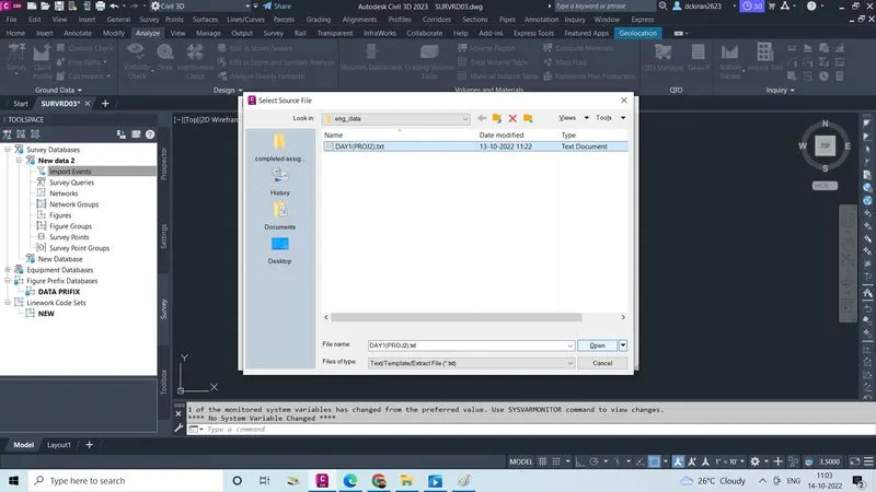
- Click on the (+) mark select the file (Day1(proj2).txt)
- Click open
- Specify the point file formate as "PNEZD"
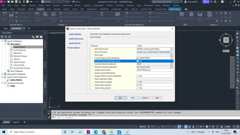
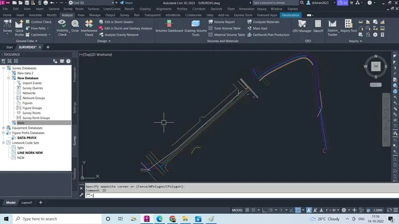
- Now click on finish
- Select and right click on the line work code sets
- Click on the "New"
- ZE enter
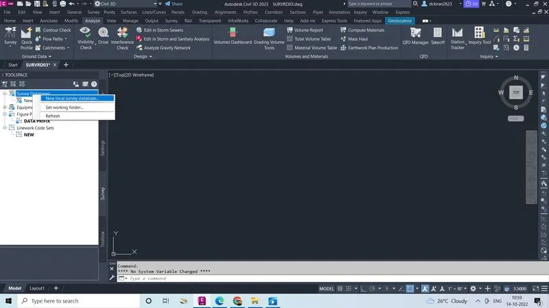
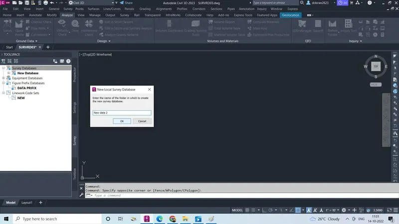
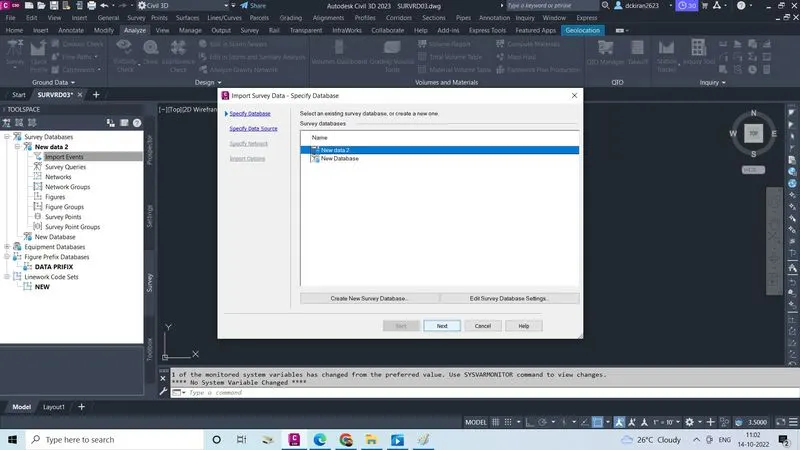
- Go to file, click on new
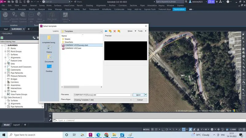
- Select one template file which is provided by the company (skill-lync/week7/downloaded fromdashboard/support/template/company XYZ(survey) click open
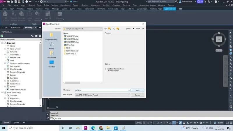
- TYpe CTRL+S Give name as DTM as .DWG form
- Save the file in a proper folder (skill-lync/week7/completed assignment)
- Click on save
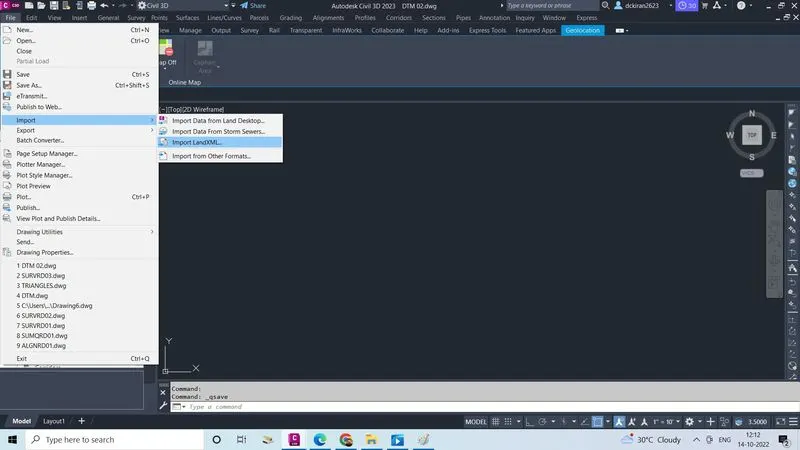
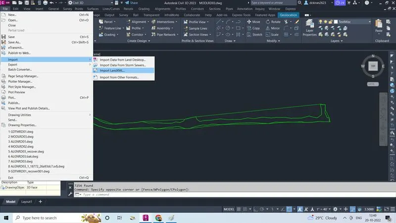
- Click on the file
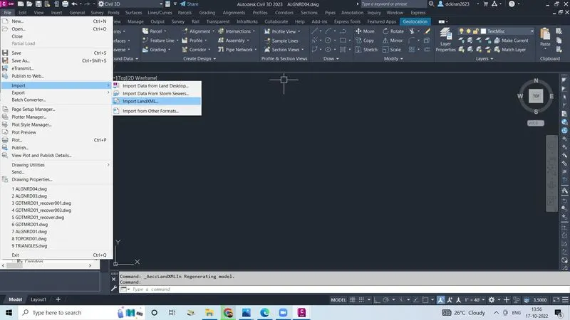
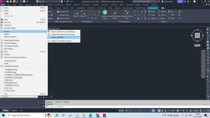
- Click on import
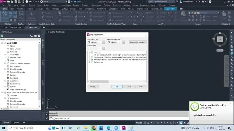
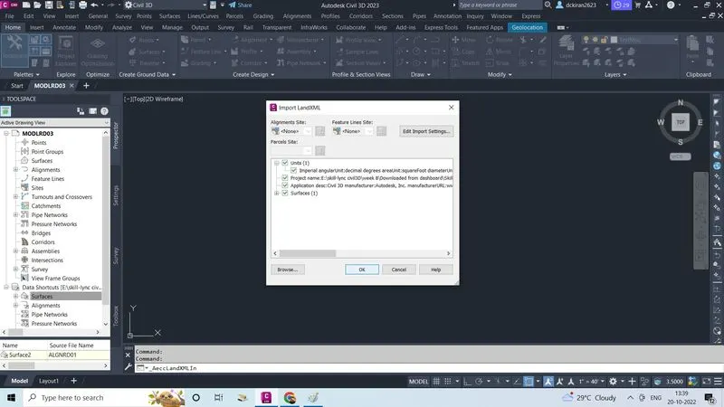
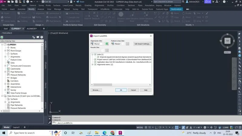
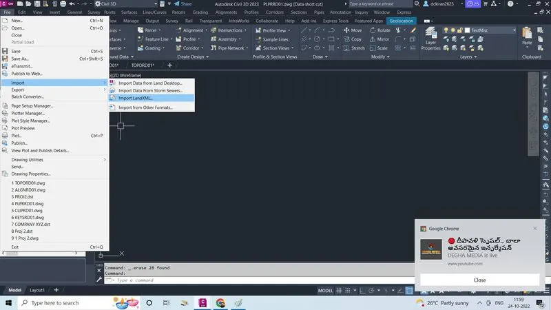
- Click on importlandXML
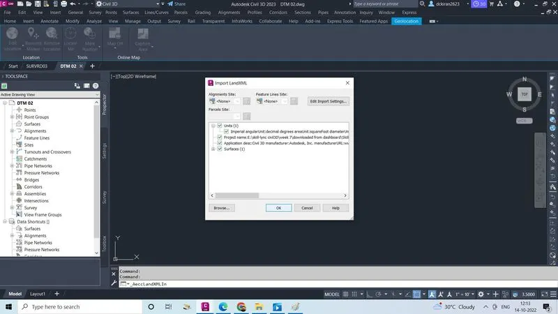
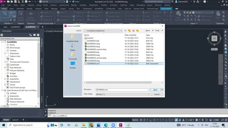
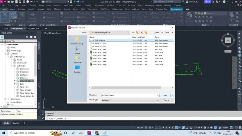
- Select on landXML file (TRIANGLE.XML) click open
- Click ok
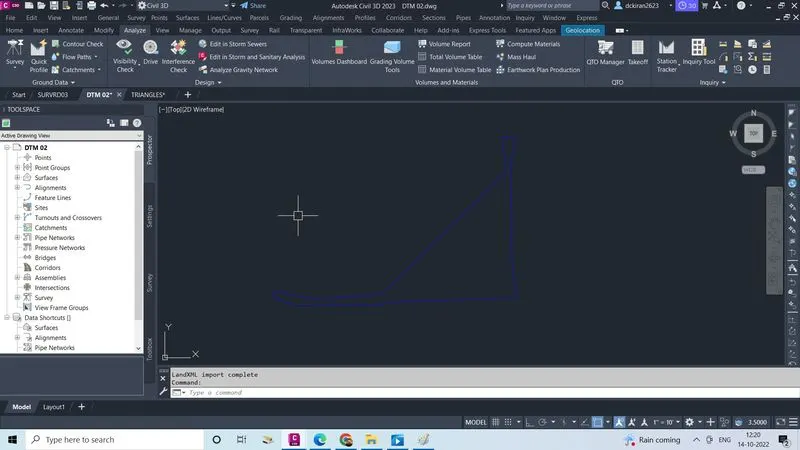
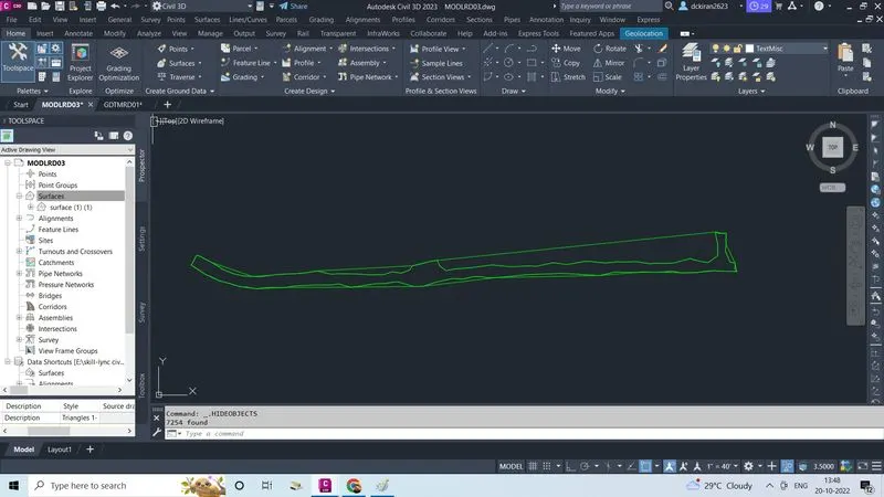
- LandXML file is reflected
- (if we want export the DTM-DEM go to DEM file toolspace/prospector, select and right click on the surface click on to export to DEM. select the path to store DEM file name (Skill-lync/week7/completed assignment)

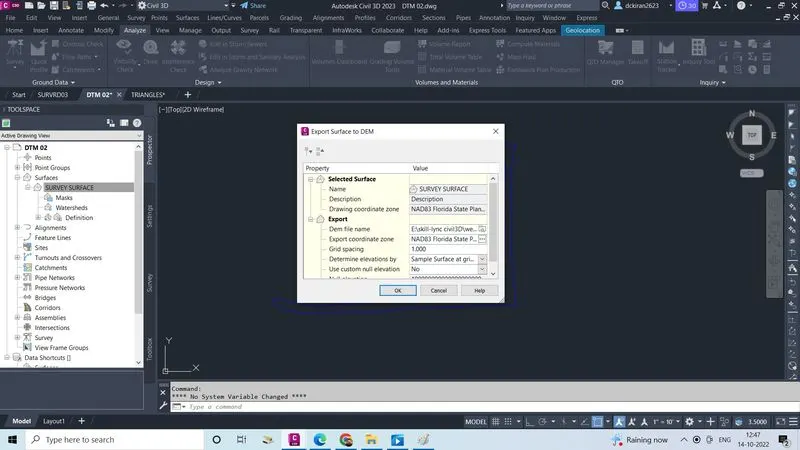
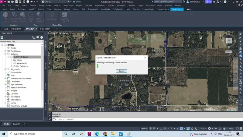
- Create the alignment first we want (ALGNRD) alignment file that we have to create first
- Go to file, click on new
- Select one template file which is given by the company (skill-lync/downloaded from dashboard/support/template/companyXYZ
- Click on ok
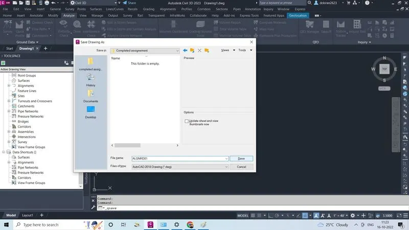
- Type command CTRL+S give a name as (ALGNRD01) As .dwg form and store in a proper folder (skill-lync/week8/completed assignment)
- Click on save
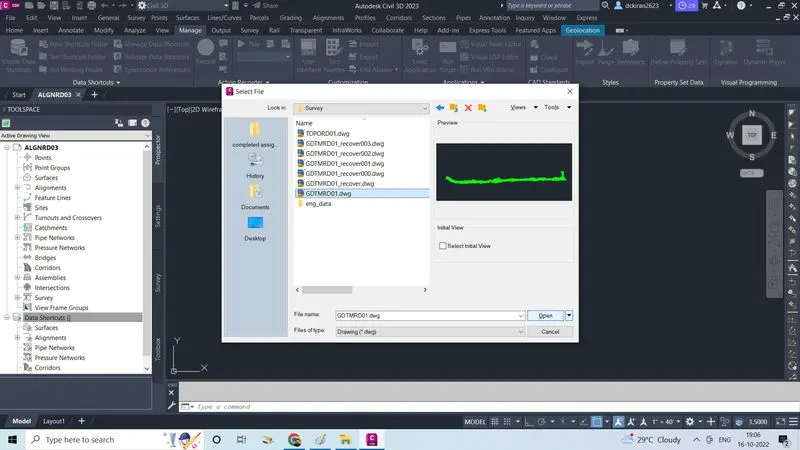
- Open the GDTMRD01 file in the civil3d which is provided by the company
- Copy the GDTMRD01 survey fille
- Create a surface for (GDTMRD01)
- Create a data shortcut,if data shortcut is not created then, export the surface to a land XML and then import into the (ALGNRD01) file
- Type command "XREF" to import the (TOPOd01) topogrphy file into a (ALGNRD01) file
- In (ALGNRD0) toolspace/setting/right click on (ALGNRD01) click on edit drawing setting give their co-ordinates as FL83-NF
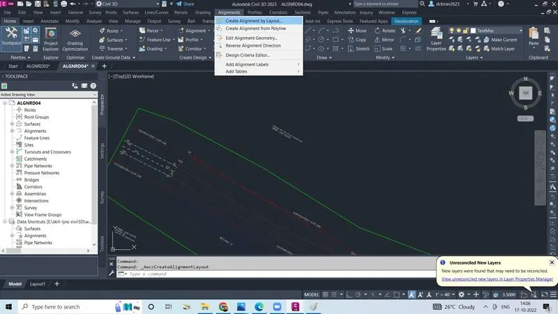
- Now create the alignment, click on create alignment by layout
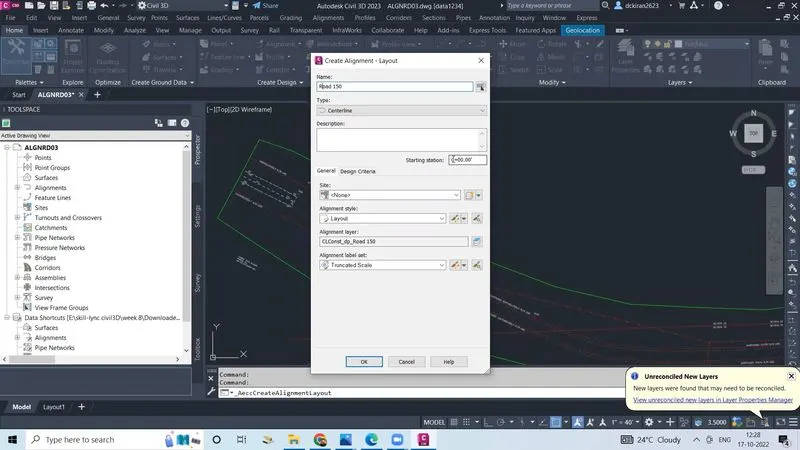
- Give name Road150,click ok
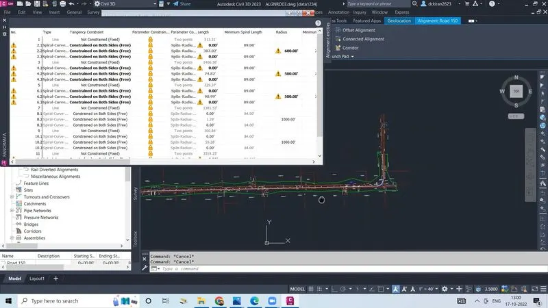
- Draw an alignment, and give a proper radius
- Now alignment is done
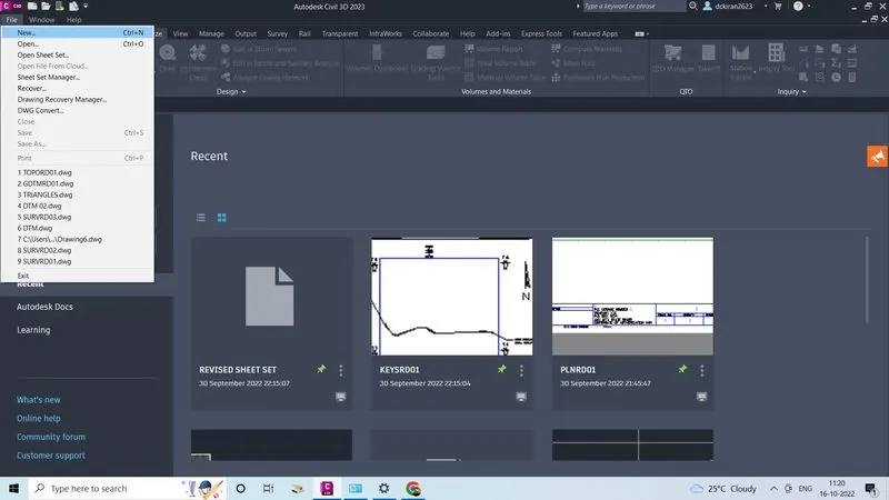
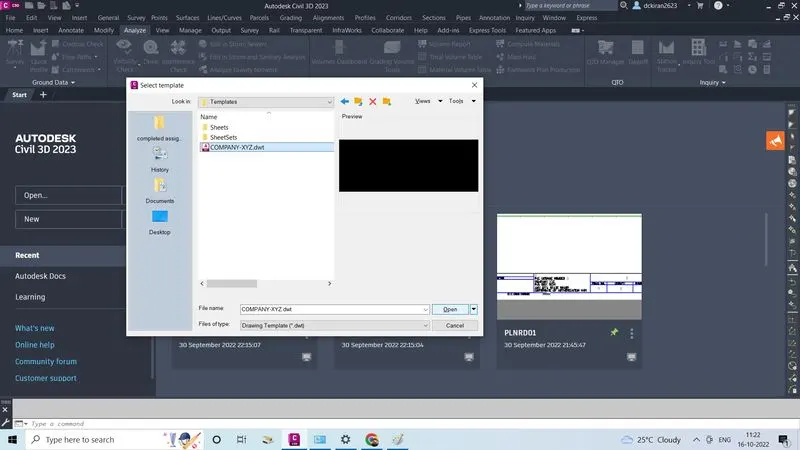
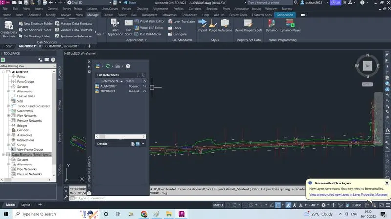
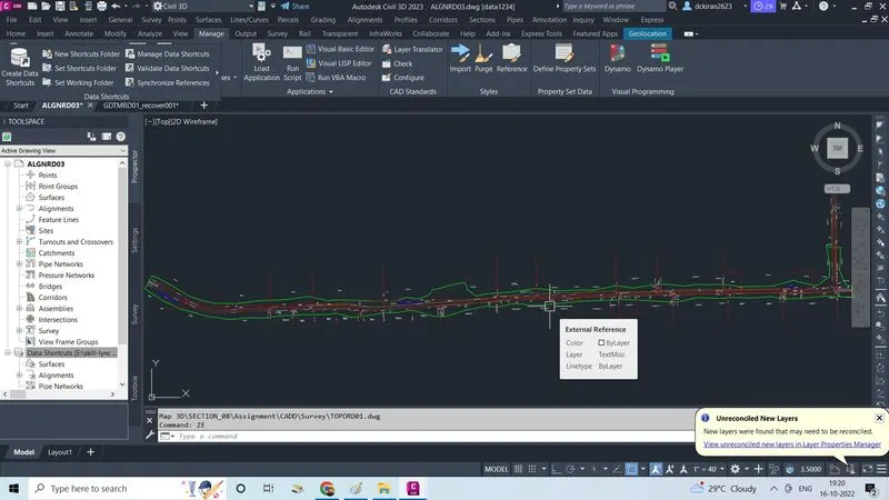
- After creating an alignment
- Now we have to add the superelevation
- First select the alignment
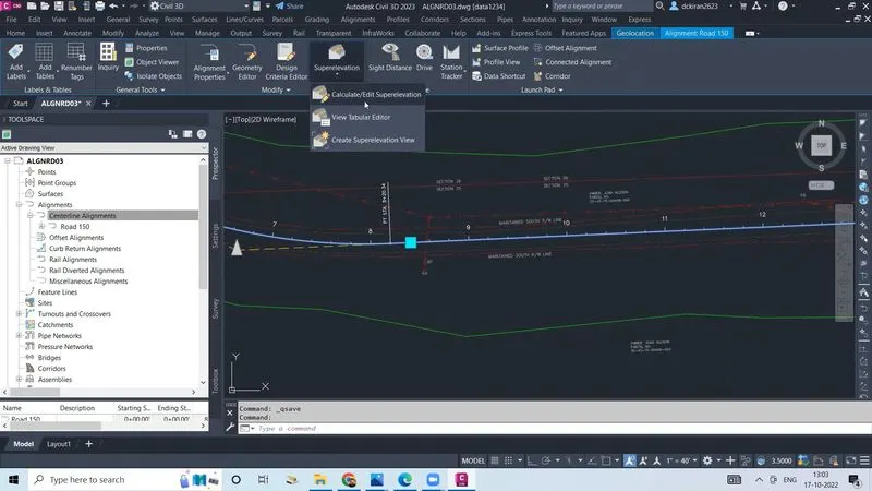
- Click on the superelevation
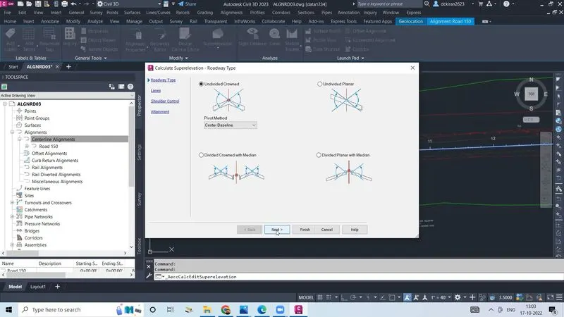
- Click on the calculate/edit superelevation dailogbox will open
- Make checkmark on the undivided crowned click on next
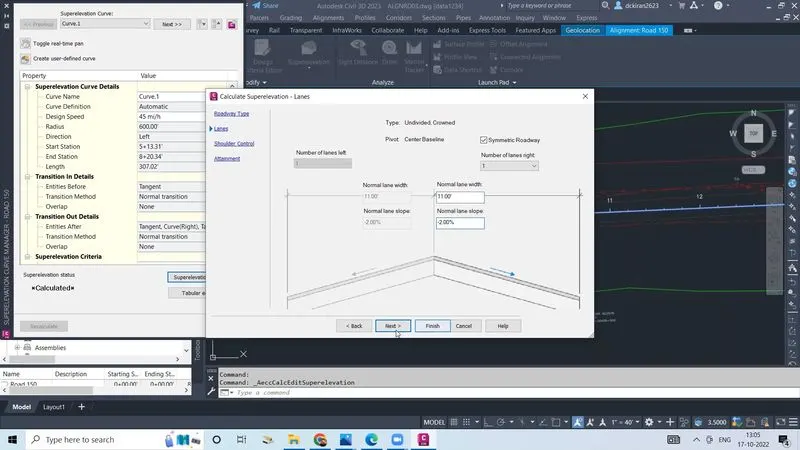
- Set the no of lanes, Give the normal lanes width as 11' as per the TCS and normal lane slope as -2% and click on next
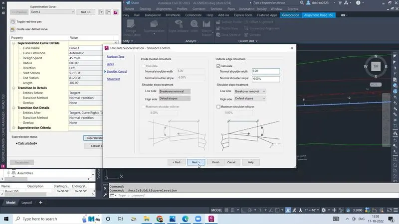
- Give the normal shoulder path width is 6' and slope is -6% as per the TCS and click next
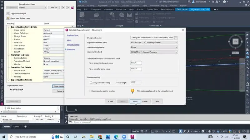
- Check mark on automatically resolve overlap
- Click on finish
- Now superelevation is calculated
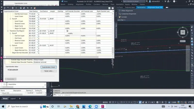
- Note: Assemblies, subassemblies and coridor are created in modling file (MODLRD) file
- First we have to create a (MODLRD) file
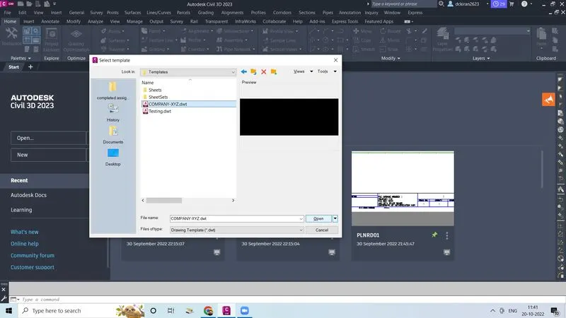
- go to file
- click on new
- select one template file company XYZ which is provided by the company (skill-lync/week9/support/template/company-xyz)
- Click open
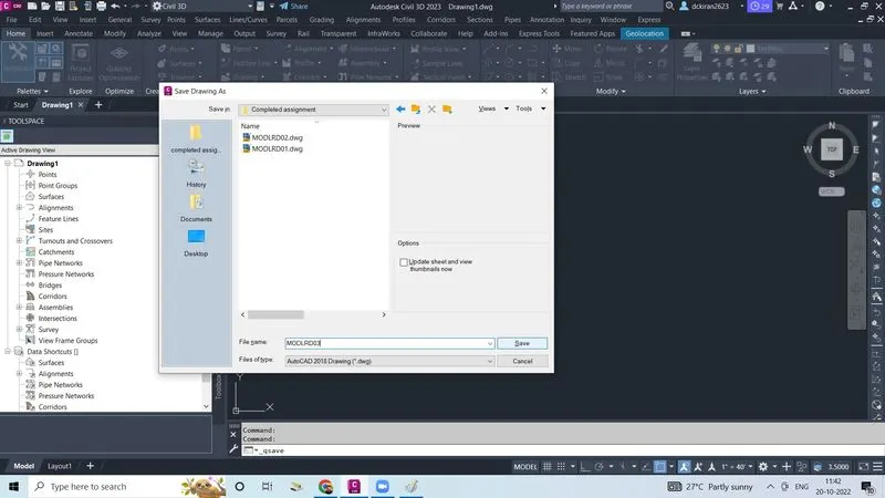
- Type command CTRl+S give a name as (GDTMRD01) and store in a partical folder (skill-lync/week9/completed assignment)
- Click on the save
- Instead of creating data shortcut lets do another method
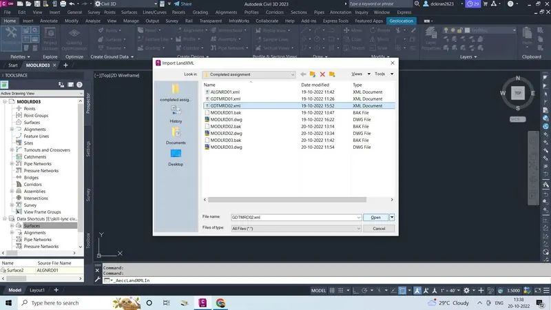
- Open the (DTMRD) survey file in the civil3D and create a surface of (DTMRD) and export it into a land XML file
- Again the import (DTMRD) XML file into (MODLRD) file
- Also we want alignment,profile so open the (TOPORD) file in the civil3D and export into landXML file and again import the (TOPRD) file XML into a (MODLRD) file and create profile in the (MODLRD) file
- Click on the profile, click on create a layout by surface
- Select the alignment and already surface is selected which is created
- Click on draw in profile view, give peofile view name, select profile view style,click next
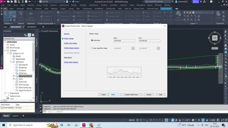
- In station range,make dot mark on automatic click next
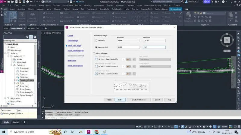
- Give Profile view height, make dot mark on user specified
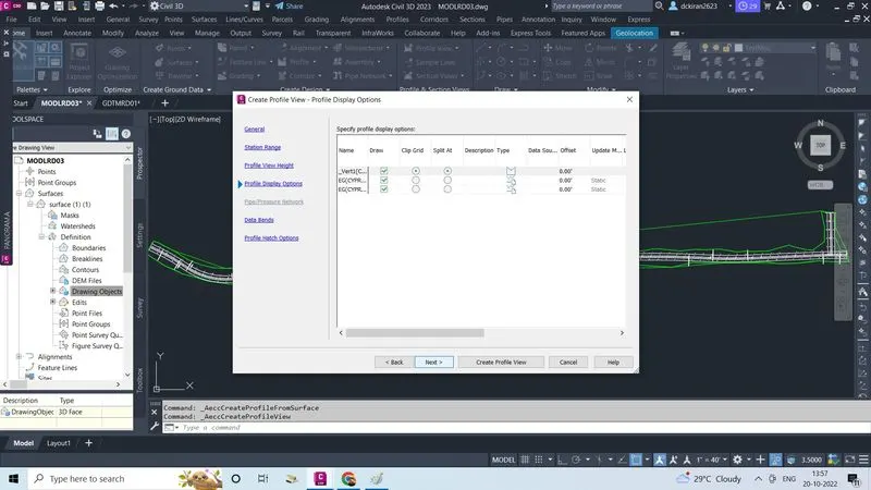
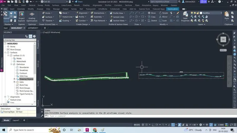
- Click next, and click on create profile view
- Now start to create the assemblies and subassemblies
- Click on assembly/ create assembly
- Give a name as "TCD -1 assembly" click on ok
- Click on somewhere to create the subassembly
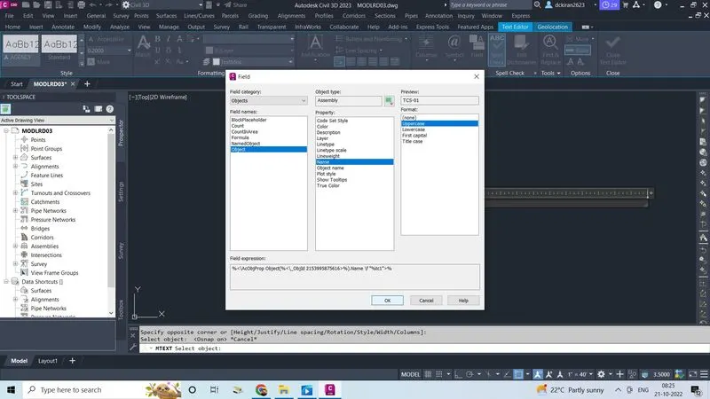
- Type command "MT" after tyle CTRL+F select the object infield categary/in object type click on green mark and go and click on the assembly mark automatticaly dailog bpx will open there we have to select name in preview we want uppercase
- Click on ok
- Select the assembly click on the tool palette
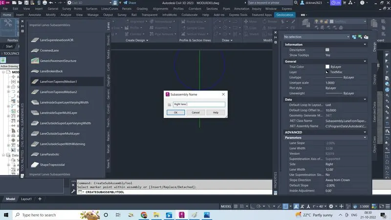
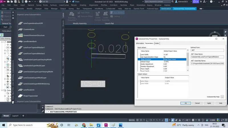
- Tool box will open in the lane section select the "lane from tapered median 1or2" again properties box will open
- Click on the mark,if the text size is big then select the text and right click, click on label properties their we can edit
- If lane text is big then select and right click on the subbassembly properties their we can edit
- Now we have to create the shoulder
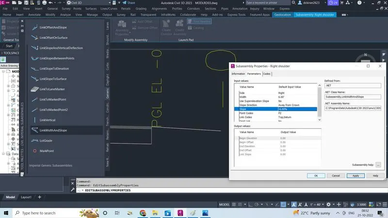
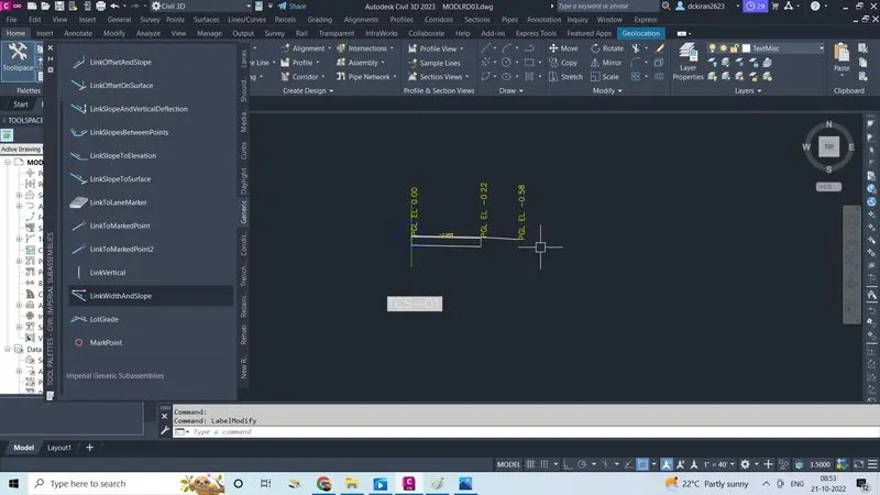
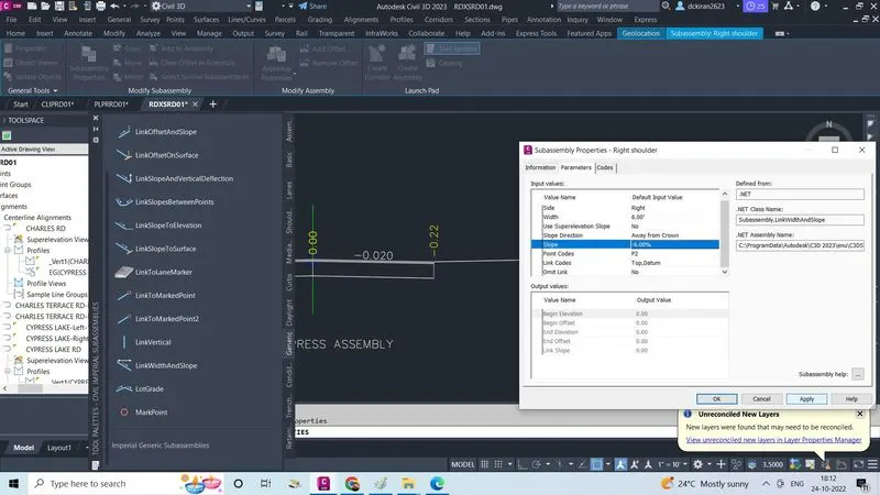
- Click on the assembly/toolpalet/ in the generic/ select link width and slope and click on the right lane, then select the shoulder and right click/subassembly properties/parameter here we can change the width of the shoulder and slope as per the TCS Click apply and ok
- Now we have do cut and fill so
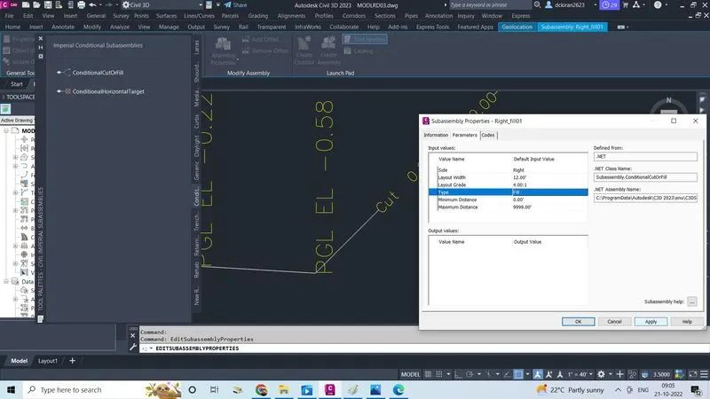
- Click on the assembly/tool palet/in the condition/ select condition cut or fill create the cut and fill 1:4 Click apply and ok
- Now we have to add the ditch so
- Go on the generic/link width and slope/ Click on the cut fill line/ give slope, width of -25% or 25% and 8' Click apply and ok
- Go on the Condition selection/select condition cut and fill
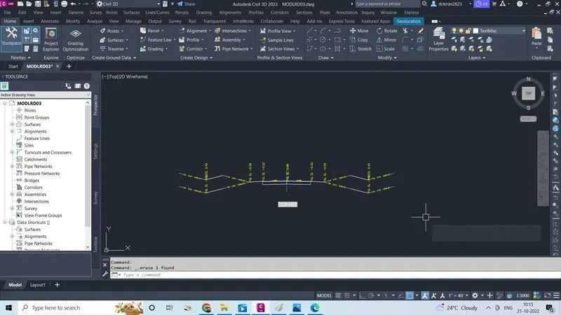
- Same thing mirror all the right subassembly to the left side
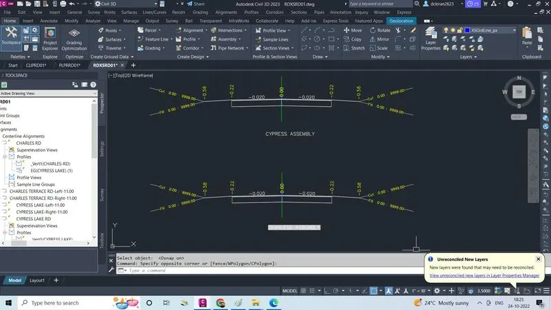
- Then assembly is created
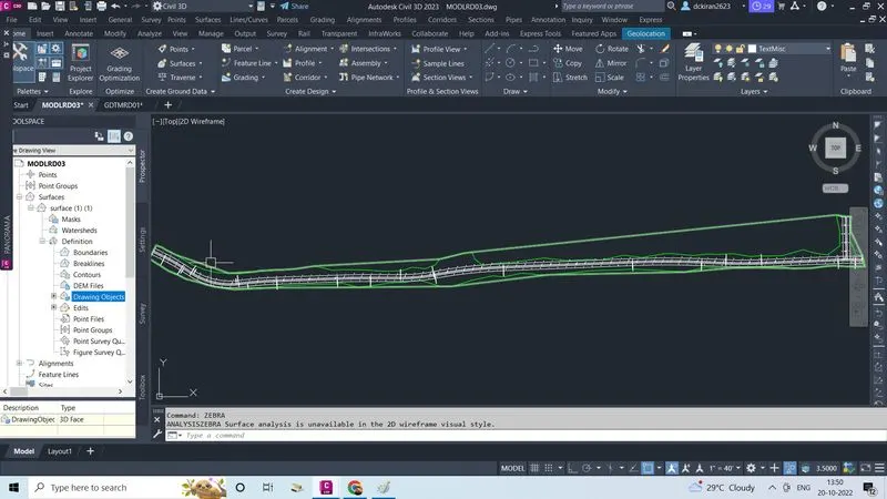
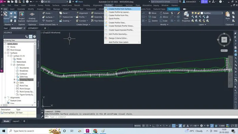
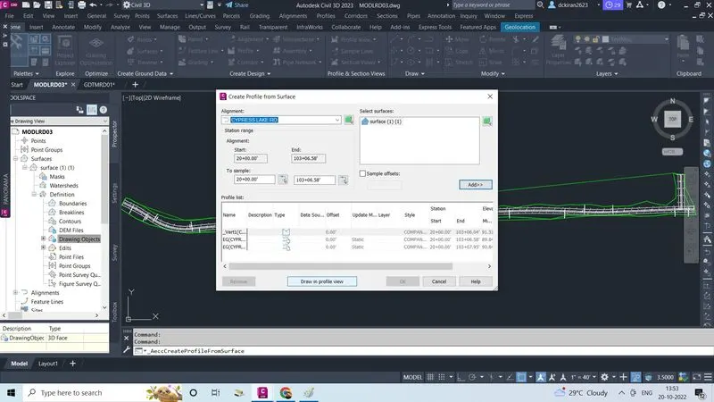
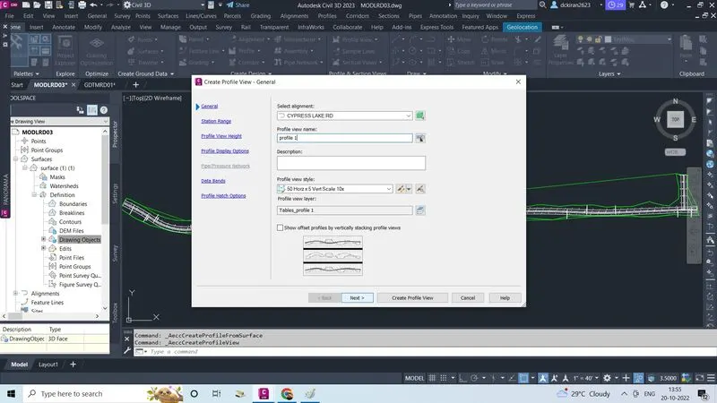
- After creating an assembly
- Now we have to create a corridor
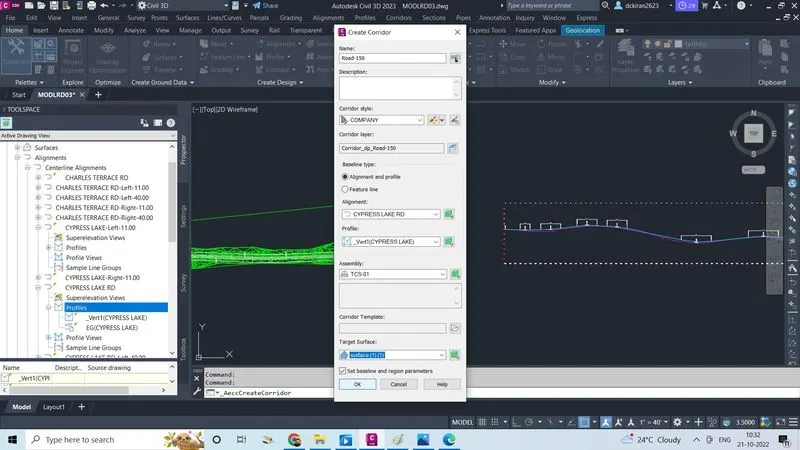
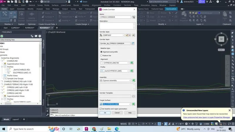
- Click on corridor/corridor, give name as road 150 select the proper alignment which exist in profile(cypress lake) as well as select profile which we created (vertical profile)
- Select the proper assembly that we created as (TCS-1)
- Select the target surface (survey surface) which we created
- Click ok
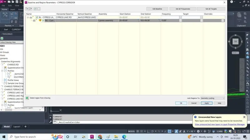
- Baseline and region parameter dailog box will open in that
- Add the frequency of along tangent,along curve,along spiral,along vertical curves, click ok
- Check the target and its set
- Click ok
- Click apply and ok
- Corridor is created
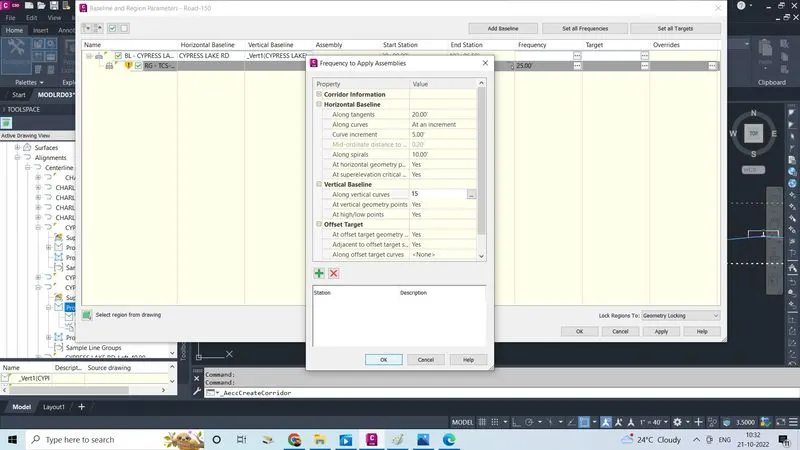
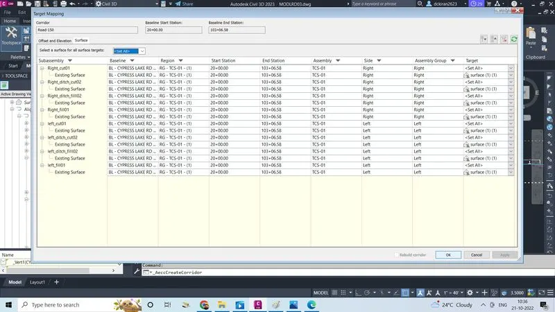
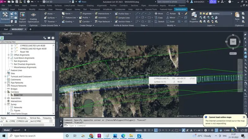
- Now we have to create intersection and pond tie on given station , so
- We have to create a new alignment, profile, assembly for that
- Click on alignment /click on create connected alignments
- Select the 1st alignment and 2nd alignment and pick a location to connect alignment
- Give a name as "CA right side"
- Select the curve group type as a circular fillet, radius 30, offset 0 and connection overlap is 20' click ok
- Do the same for left side also
- Take a line to Split the region
- After drawing the perpendicular line
- Goto corridor, select and right click on Road 150, click on properties
- Add the frequency of along tangent,along curve,along spiral,along vertical curves, click ok
- Check the target and its set
- Click ok
- Click apply and ok
- Corridor is created
- Click on split region And select the region from where to where to split the region and make assembly and subassembly for splited portion also call it as TCS-3
- Make a corridor for TCS-3 also and set the target click on apply and ok
- Intersection and pond tie in (54+00 to 54+80) is done
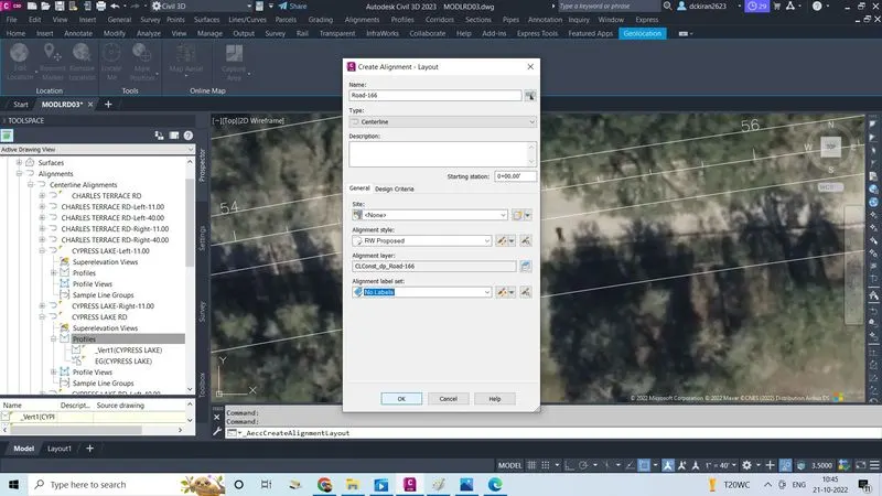
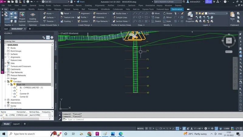
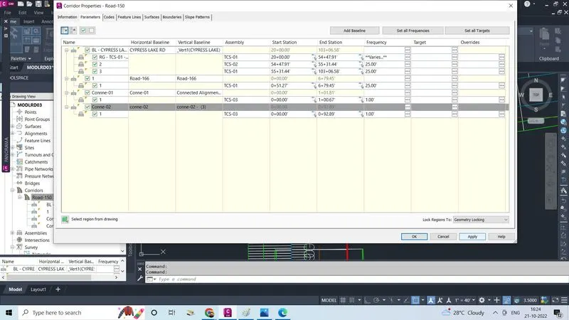
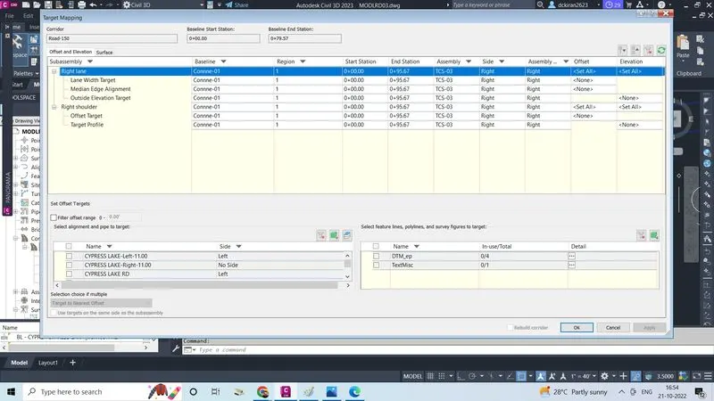
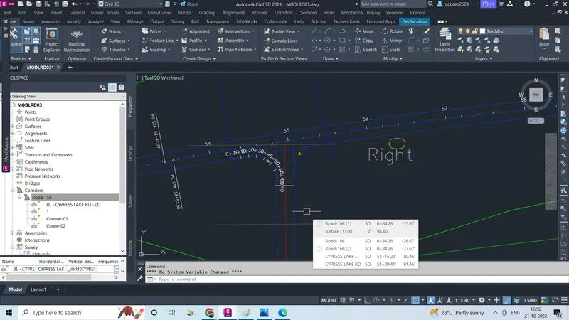
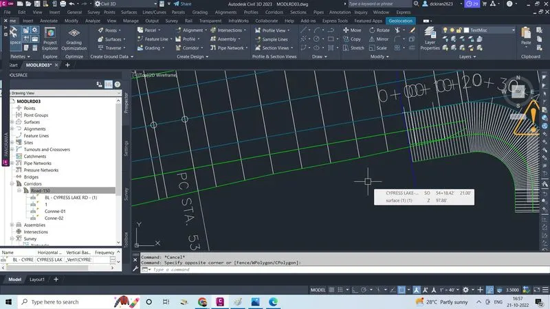
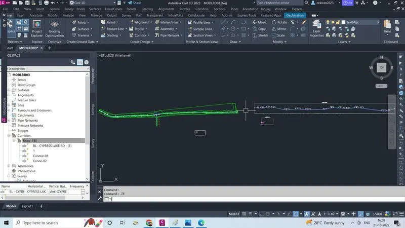
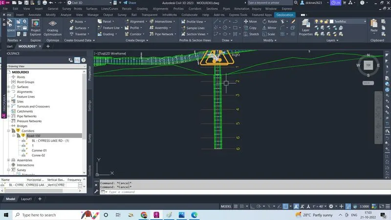
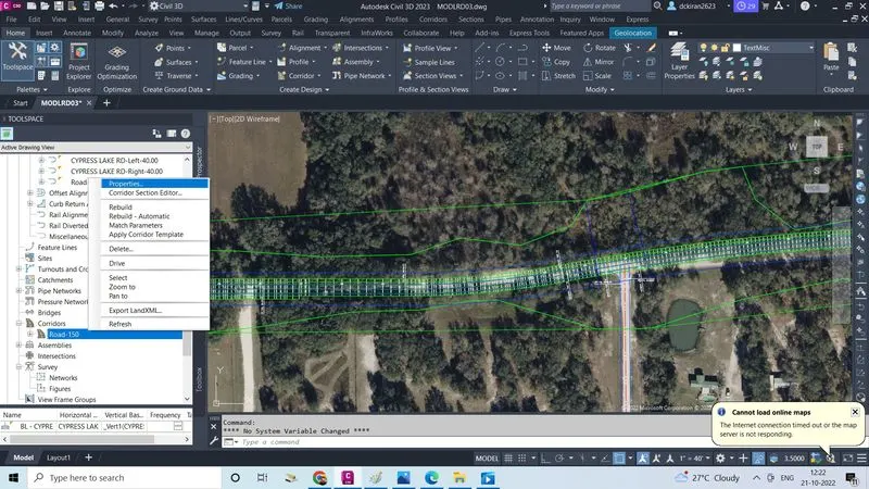
- In MODLRD file toolspace/prospector/select and right click on the created corridor( Road150) click on the properties
- One dailogbox will appear in that click on the surface
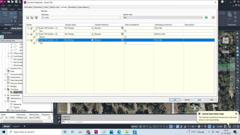
- Click on the create a corridor surface mark and select the specify code as "Top"click on (+) mark and make check mark on the add base line and in overhang correction, select top links
- Click on the create a corridor surface mark and select the specify code as "Datum"click on (+) mark and make check mark on the add base line and in overhang correction, select Bottom links
- Click apply and ok
- Open the plansheets in the civil3D which is provided by the company
- Go to file
- Click on open
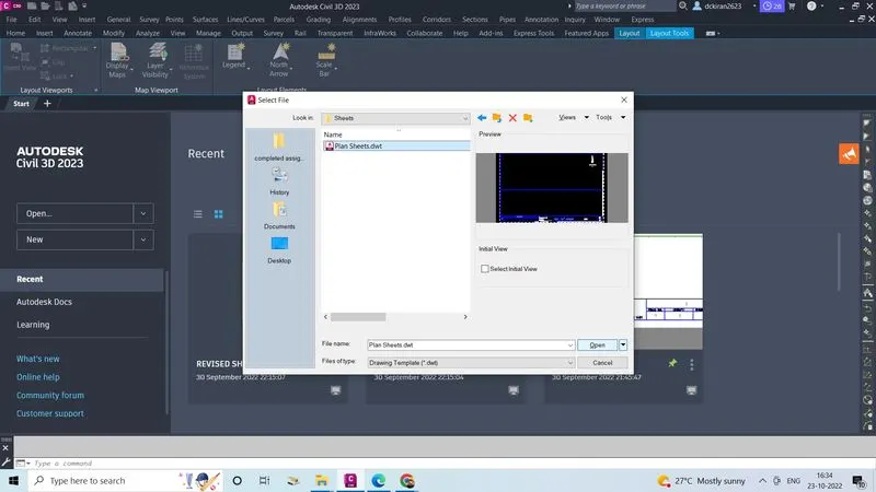
- Chose the plansheets .dwt file which is in the skill-lync /week 11/downloaded from dashboard/ support/ sheets/plan sheets dwt
- Click open
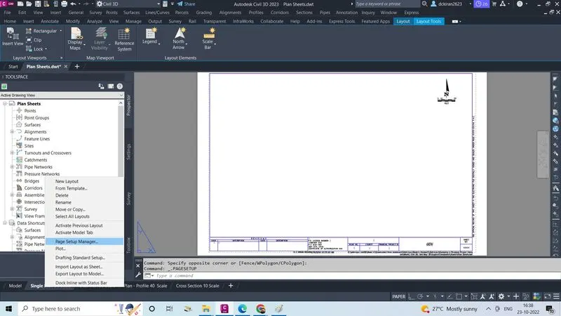
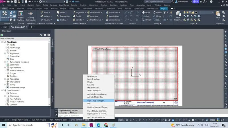
- Select and right click on the single plan scale
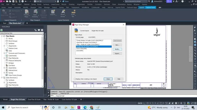
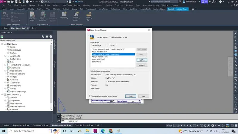
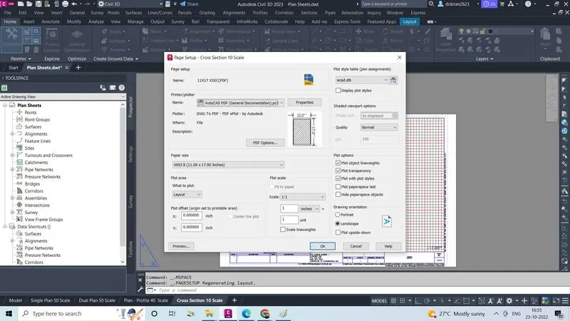
- Click on the page setup manager
- Click on the modify,view port toolbox will open
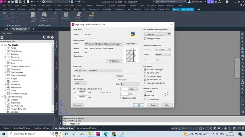
- Check the printer name give correctly
- Give the paper size Ansi bleed B(11x17 inches)
- Give plot style table (pen assignment) as acad.stb
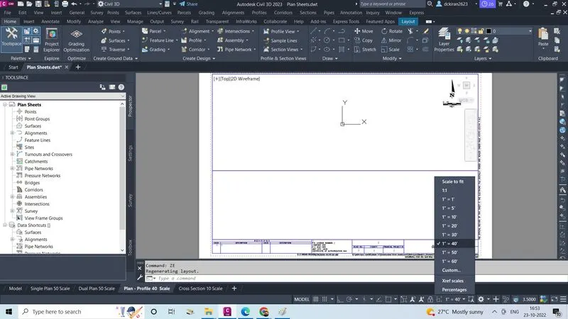
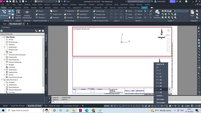
- Select landscape and, now all are in proper so click ok,click on close set the scale and lock it and set the properties
- Do the same procedure for dual plan 50 scale,plan-profile 40 scale, cross section 10 scale viewport to the correct property
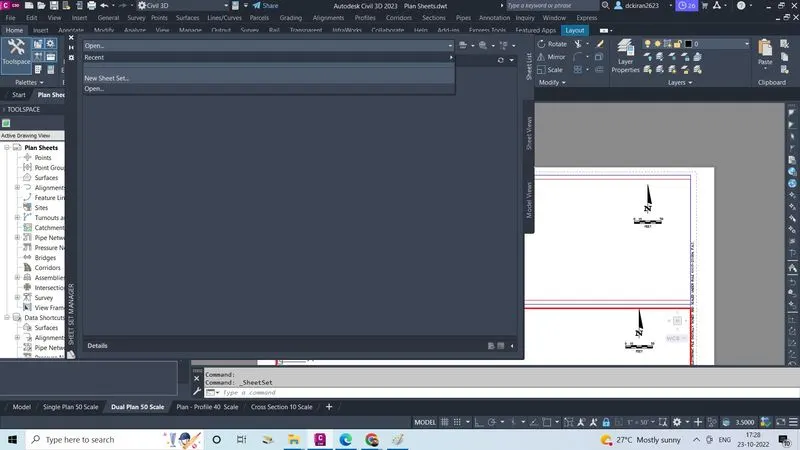
- Type command CTRL+4 ,sheet set manager will open
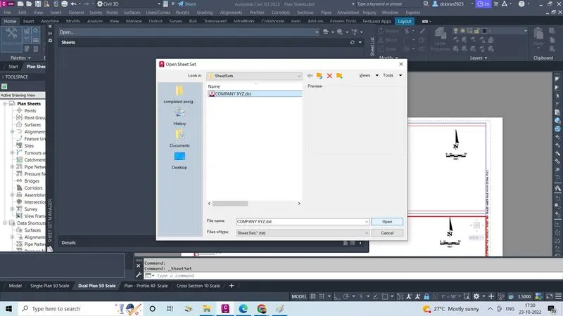
- Click on open
- One fill will arrive in that go in the skill-lync/week11/downloaded from dash board/suppport/template/in that Company .dst is there select that click on open
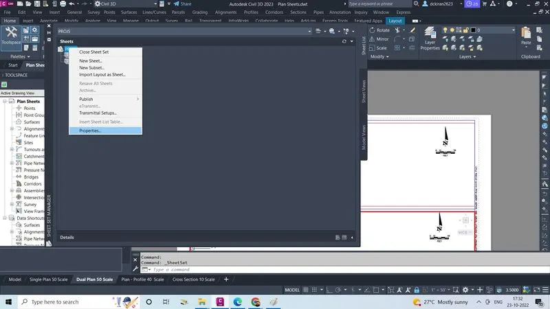
- Select and right click on that import .dst file (companyn XYZ) PROJ2
- Click on properties
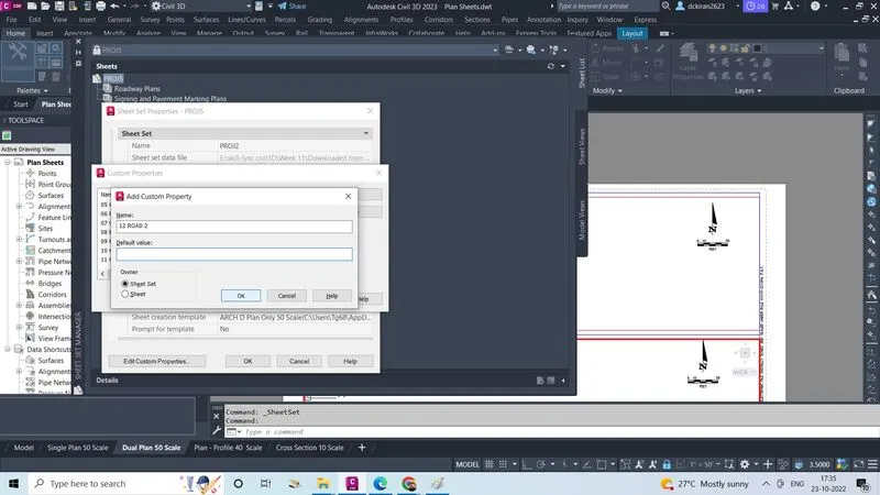
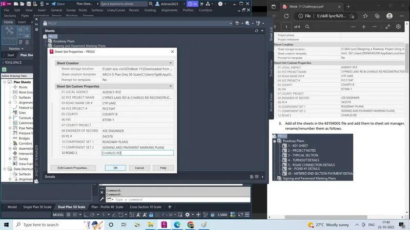
- Give the name as PROJ2 as said by the company
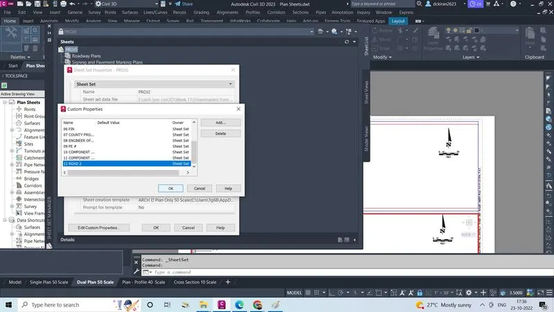
- Enter all the custom properties as said and given by the company
- Click on ok
- Now its created
- Open the KEYSRD01 file in the civil3D
- Select all the sheets right click
- Click on the import layout as sheet
- Click on import checked
- It is imported in the sheet set manager
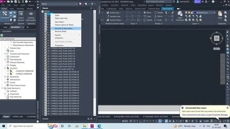
- Select and right Click on key in the sheet set manager
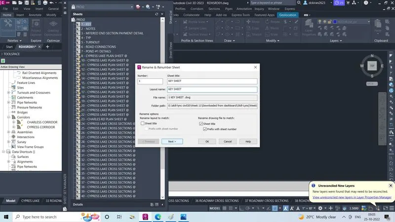
- Click on the rename and renumber
- Do the same procedure for all sheets
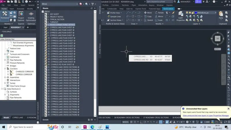
- Set in the serial wise
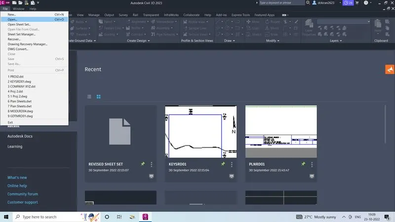
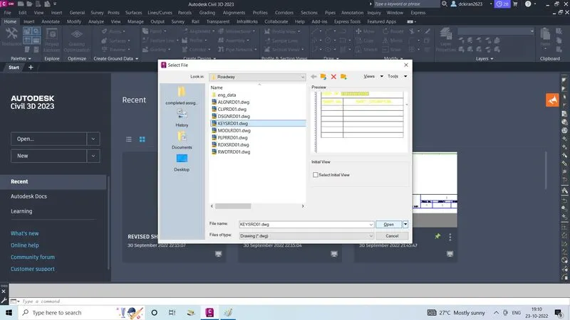
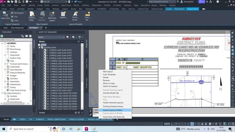
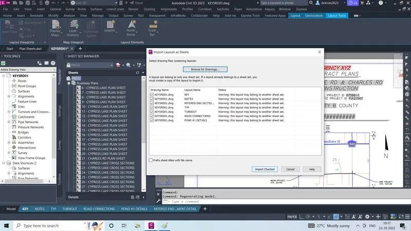
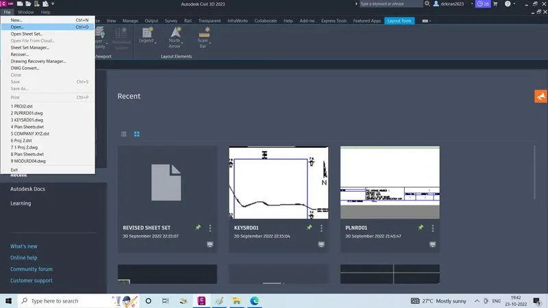
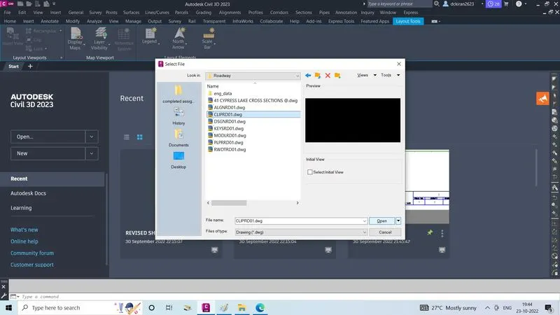
- Go to file
- Click on the open
- File manager will open select the CLIPRD01 .dwg file (skill-lync/downloaded from dashboard/week11/section11/cadd/roadway/CLIPRD01) which is provided by the company
- Click on open
- We want alignment so,open ALGNRD01 file in civil3D,by doing the same procedure
- Click on open
- we want alignment in the CLIPRD01 file so
- We want to copy the alignment by creating the data shortcut of the alignment (cypress lake and charless RD)
or
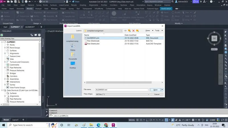
- Export both alignment into land xml file in the CLIPRD01 file
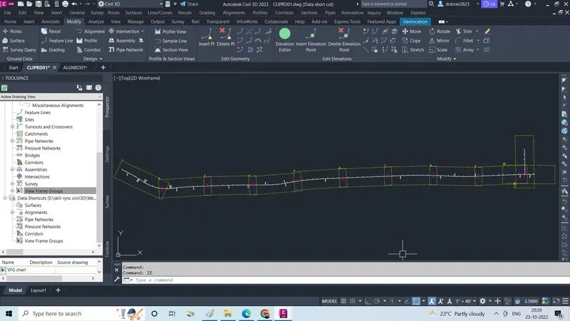
- Now create view frame
- In CLIPRD01 file toolspace/prospector/select and right click on viewframe groups
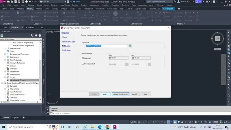
- Click on create viewframes
- Select the alignment which is created,click next
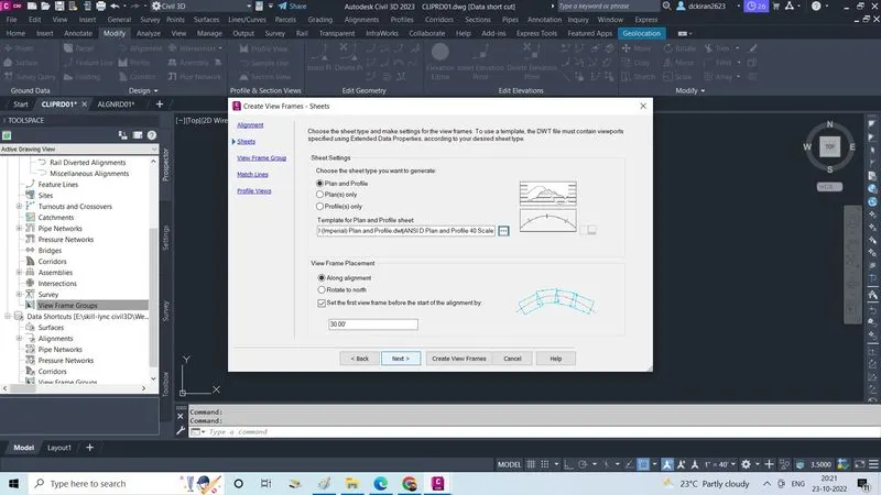
- Make dot mark plan and profile, click next
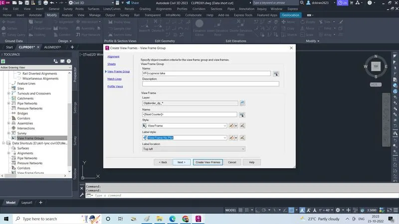
- Give the name as "VFG CYPRESS LAKE" click on next
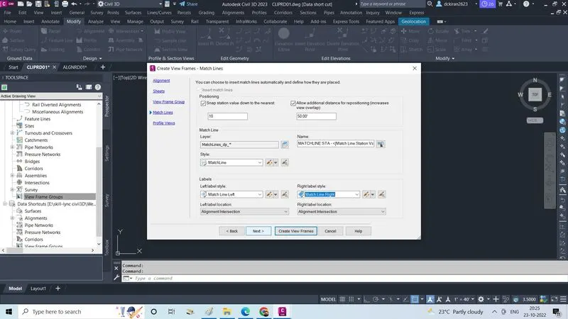
- Match line give snap station 10 and overlap is 50',click next
- Click on create viewframe
- Do the same procedure for CHARLESS RD
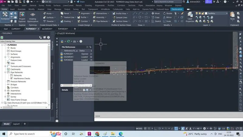
- Open PLPRD01 file in the civil3D as said by the company to create plan and profile sheets
- Import the alignment land xml in the ALGNRD01 file which is already created and exist in the (skill-lync/week11/completed assgnment)
- Click on open ,Click ok
or
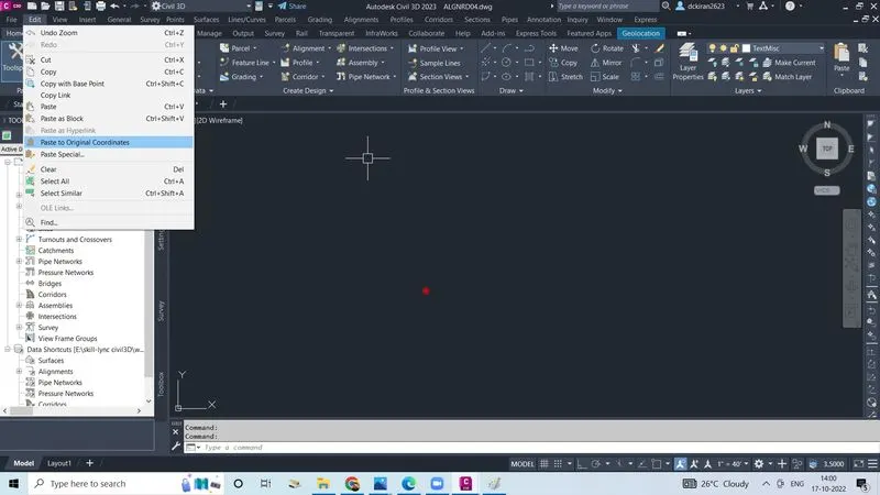
- Copy the alignment from ALGNRD01 file and paste it into orriginal co-ordinates into a PLPRD01 file
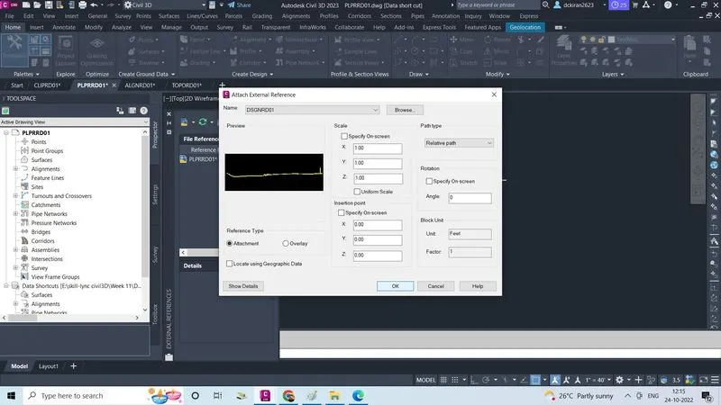
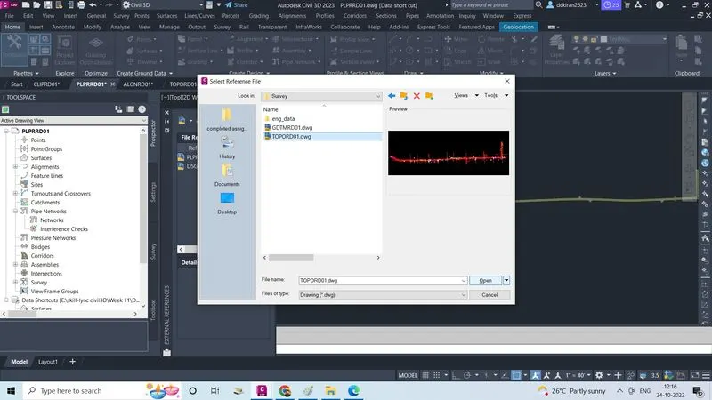
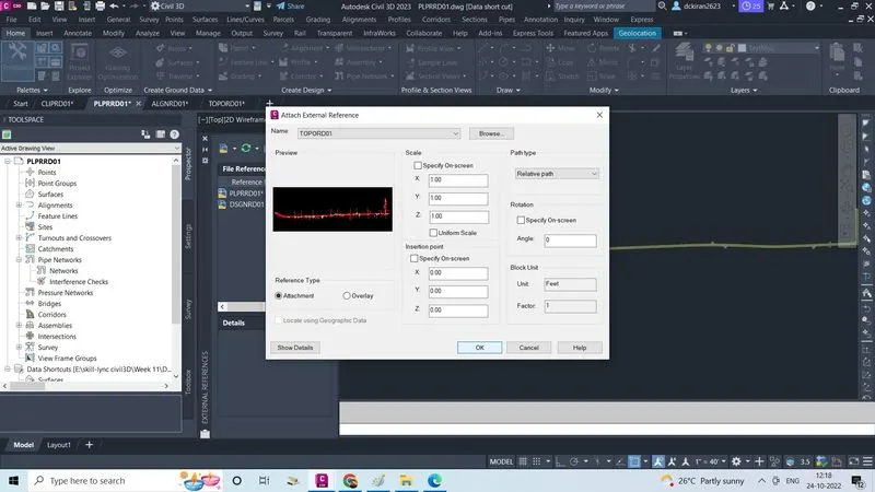
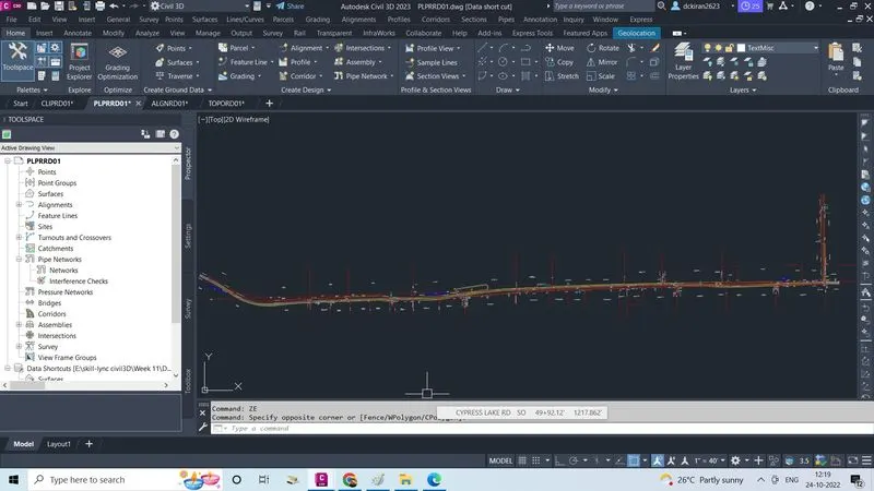
- Type command "XREF" to import the "DSNRD01 and TOPORD01"file in the CLIPRD01 file type command "XREF"to import the TOPORD01 file in the CLIPRD01 exizt in the syrvey file
- Before create viewframe lets check the profile and surfce is exist or not , ok
- Lets create viewframe in PLPRD01 file
- Go to toolspace/prospector/select and right click on the view frame groups
- Click on create viewframes again
- After creating viewframes, create a sheets
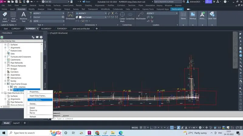
- Select and right click on cypress lake
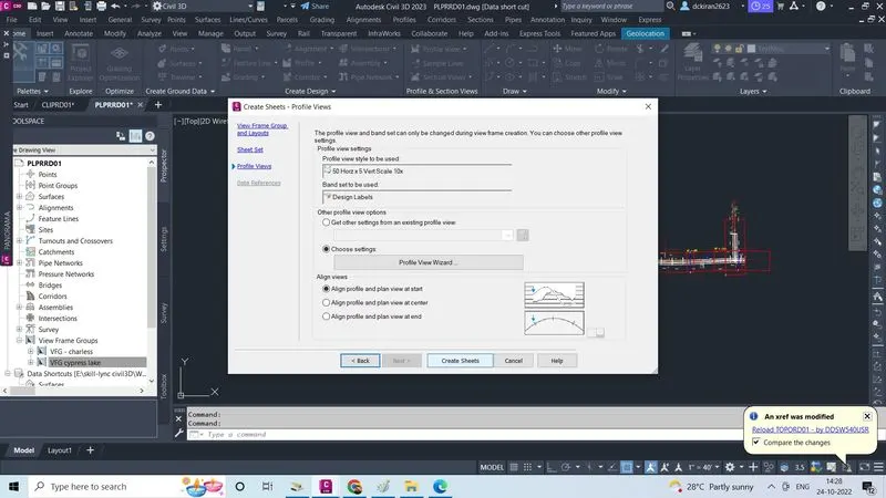
- Click on the create sheets
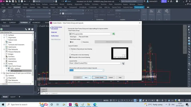
- 1st Select view frame groups as VFG CYPRESS LAKE
- Make dot mark on the all layouts in the current drawing click next
- Make dot mark on the add to existing sheet set and select existing sheets from skil-lync/week11,click next
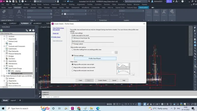
- Make dot mark on the choose setting, click on profile view wizard
- Select mean elevation inprofile view datum, click next
- Select labels in profile dispaly options, click next
- Click next
- In data band select profile 1 & 2 as vert1 (cypresslake ) click next
- Click finish
- Click on create sheets
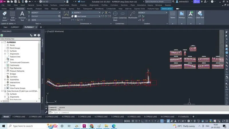
- Click somewhere plan and profile sheets us created
- Now edit some change in profile
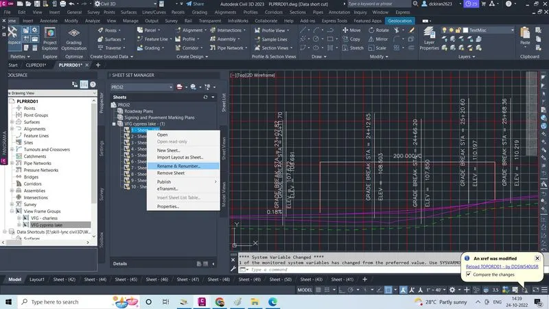
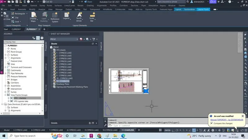
- In existing .dst file right click on sheet, click on rename and renumber give the name as cypress lake
- Click on next , do the same for all sheets plan profile sheet is created
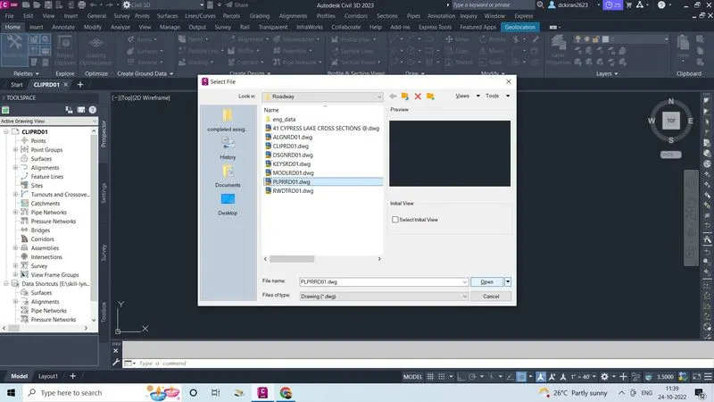
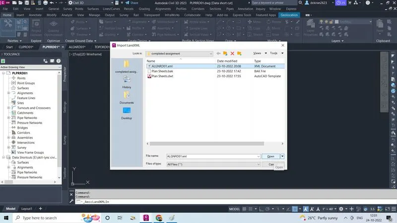
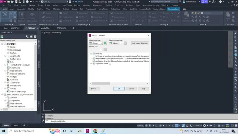
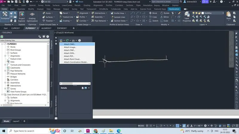
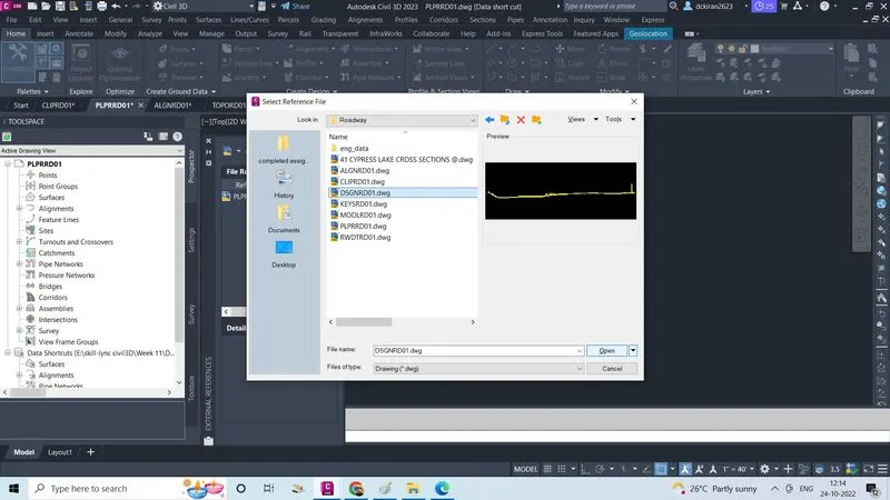
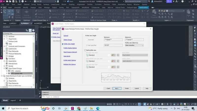
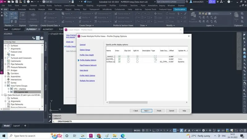
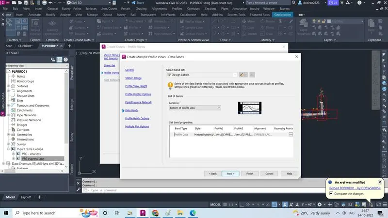
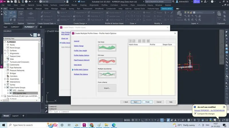
- Open the existing RDXSRD01 file in the civil3D
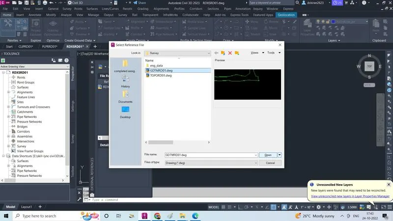
- And again by command "XREF" import the GDTMRD01 file surface file into the RDXSRD01 file
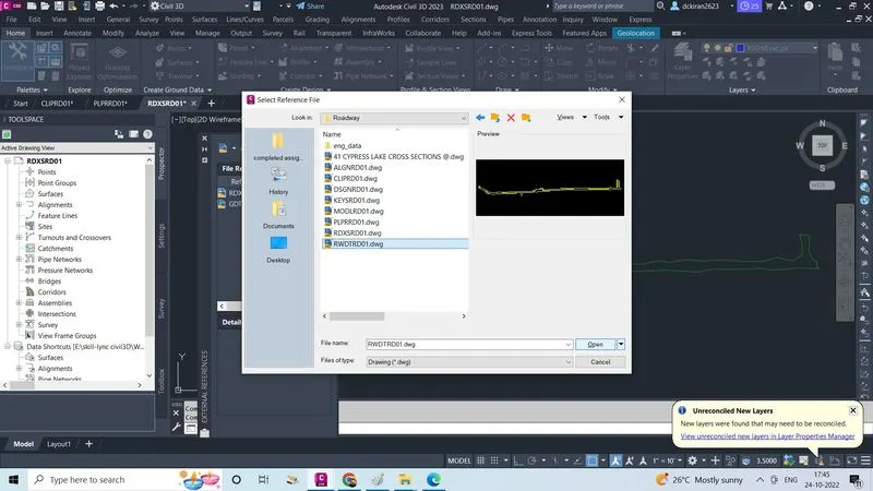
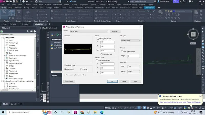
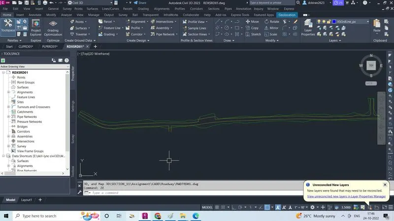
- Also import RWDTRD01 file into the RDXSRD01 file by the Command "XREF"
- Also we want alignment so
- Import the alignment XML file in the RDXSRD01 file
- To create a cross section sheet first we have to create assembly as well as corridor
- Create assembly and after
- Create corridor
- Now we have to create a Corrss section sheet
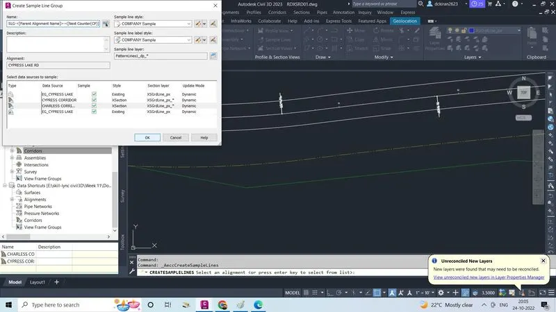
- Go to home tab ,profile and section view, select sample line and click on the alignment, sample line toolbox
- Click ok
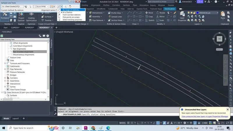
- Select 'by range of station'
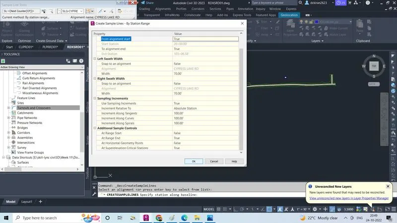
- Fill all the options in a correct way
- Make it "true "for at range end in additional sample control
- Click ok
- Your sample line is created, now we can delete unwanted sample line at a proper place it is very neccessry
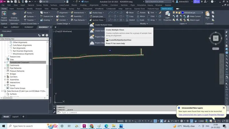
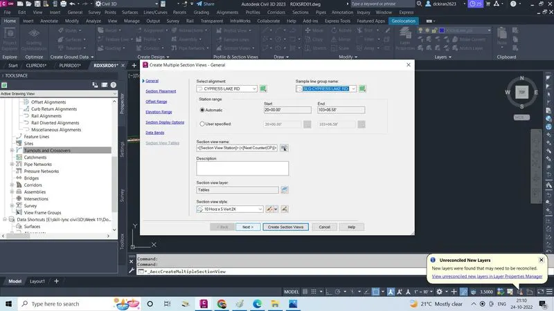
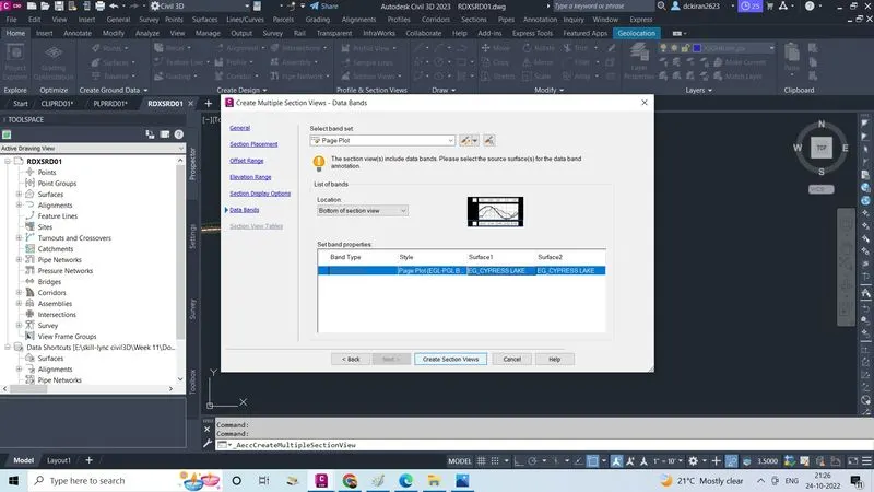
- Now click on section view , click on create multiple views
- Select the alignment, click next
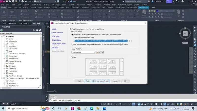
- Select the template ,plan sheet which is provided by the company, click next
- Click next
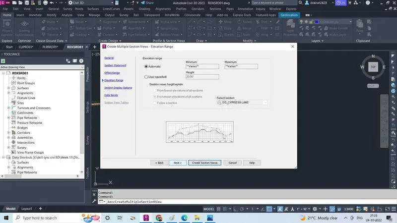
- Dot mark on the user specified give height of 20' click next
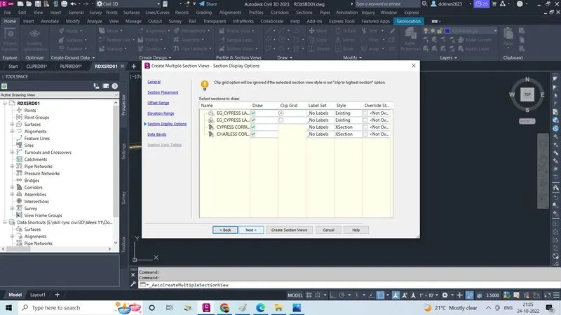
- Click next, or we can change lable style
- Select surface 1 & 2 ,Click next
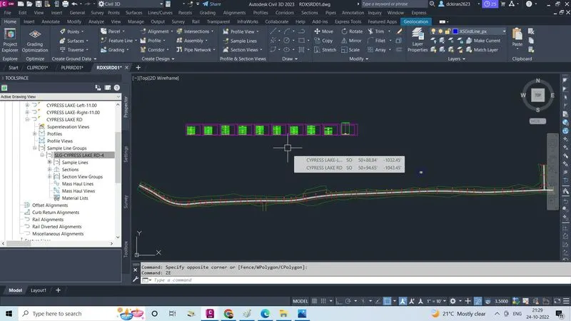
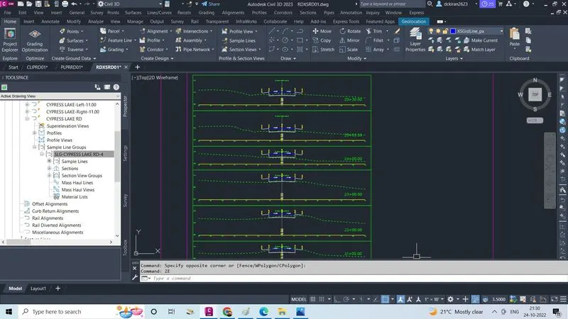
- Click on create section view
- Now we have to create section sheets so
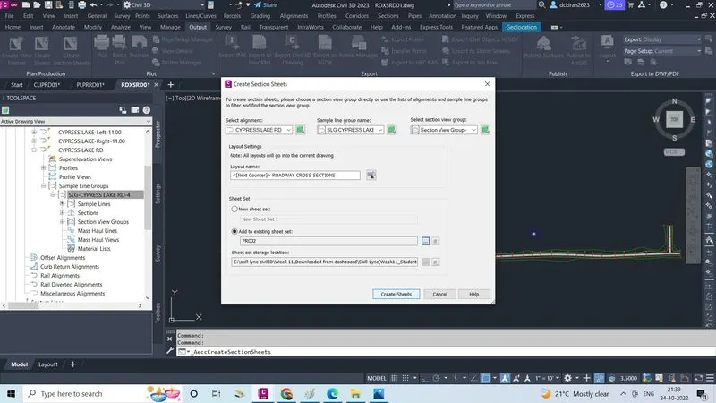
- Go on output, click on create section sheets
- Do mark on add to existing sheet set select the .dst file which is already exist in the week11/support/template/company xyz.dst (PROJ 2)
- Click on open
- Click on create sheets , now sheets is created
- Now we have set the sheet in a serial wise and with a proper name so
- Select and right click
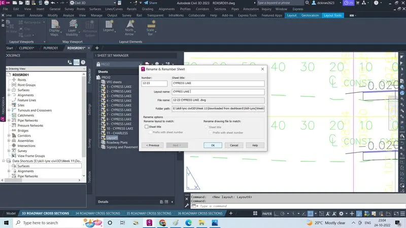
- Click on the rename na renumber
- Give the proper number and proper name, click on next, like wise check to all and do the same procedure at last click ok
- Now all sheets are in renamed and renumber as said by the company
- Open KEYSRD01 file in civil3D
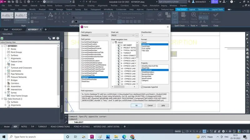
- Click on the sheet no after click on the field or CTRL+F
- Select the field catagory sheetset and related sheet are refelected their select the key sheet 1st
- Select the formate in uppercase, select the property related to that
- Click on ok
- Repeat the same procedure for all description
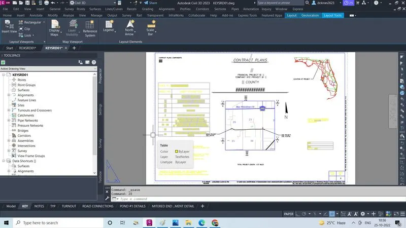
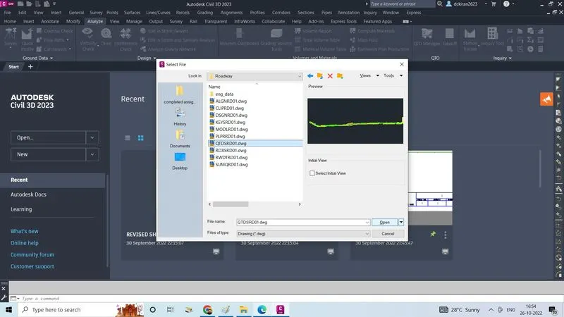
- Open the QTDSRD01 .dwg file in the civil3d
- Go to file ,click on open
- Select the QTDSRD01 file which is already exit in the skill-lunc/week12/downloaded from dashboard/cadd/roadway/QTDSRd01 file
- Click on open
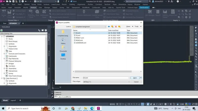
- To calculate volume we want appropriate surface so there is no of surface in QTDSRD01 file which is already exist in othere ,dwg file so we will export that surfaces like,subgrade, pond,road,EG,FG XML file and import it into the QTDSRD01 file or we can add by creating the data shortcut
- Export it into land XML like subgrade ,pond,road,EG,FG,import it into a QTDSRD01 file
- Now go to analyse, click on volume dashboard panaroma dailog will open
- Click on create new volume surface
- We have to calculate Volume of pond, subgrade, road,FG,EG
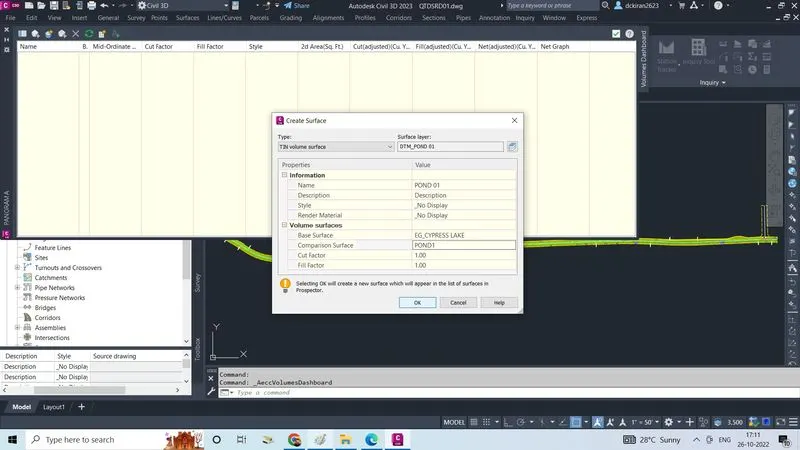
- So give the name "POND01"
- In volume surface give the base surface as EG cypress lake
- Give the comparision surface as POND1
- Click on ok
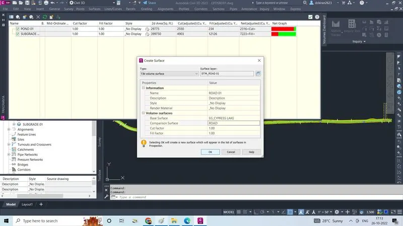
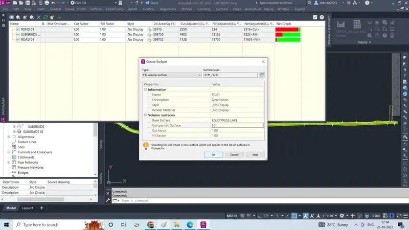
- Like wise do the same procedure for all to calculate volume of surace
- Volume is calculated for those surface
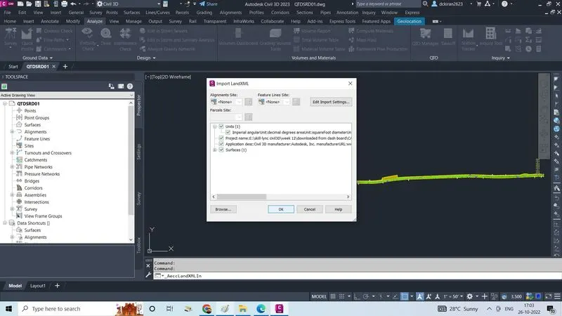
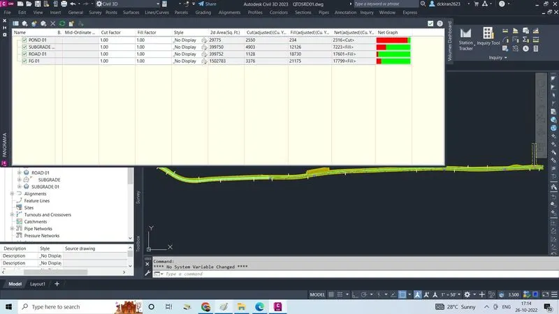
- Before performance of quantity take-off first we have to assign the quantites by seeing the payitems of the respective quantites which is provided by the company
- Go to analysis which is provided by the company
- Go to analysis, click on QTO manger
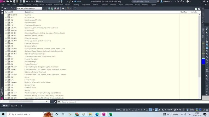
- Import the pay items in the QTO manager
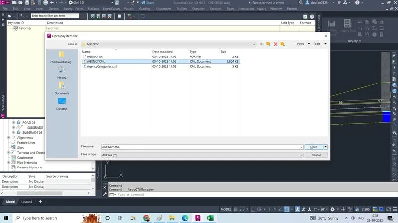
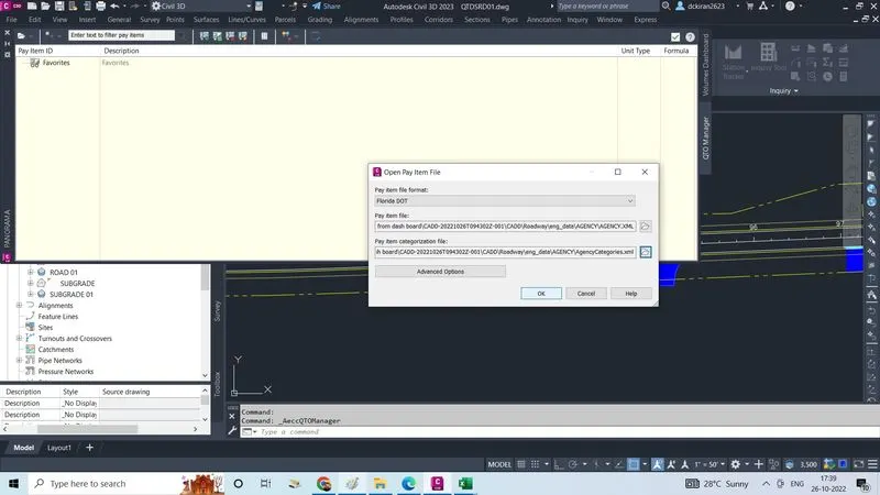
- Select pay items file formate as FLORIDA DOT and select pay item file as AGENCY XML file exist in the Week12/cadd/agency Xml
- Select pay item categorization file as ANENCY categories XML exist in week12
- Click on ok
- Start assiging the pay items to quantites pf clearing and grubbing
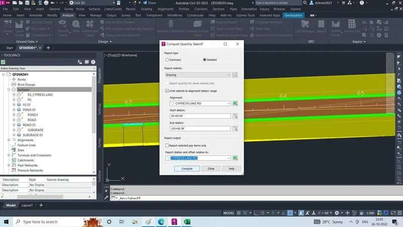
- Select and right click on clearing and grubbing of (payitmes 011011) click on the take off
- Click on deatailed, select drawing
- Select the station and station and offset realtive to as cypress lake RD
- Click on compute
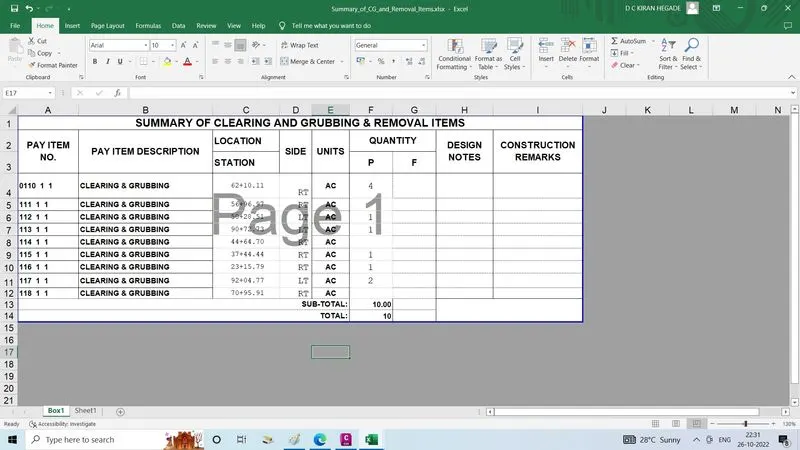
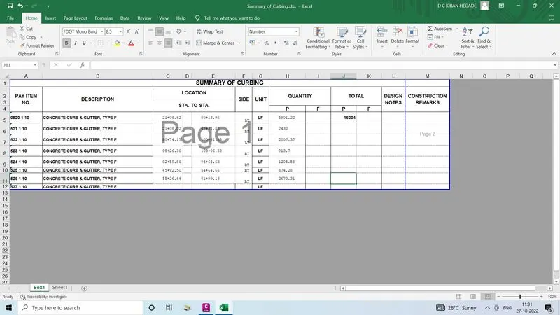
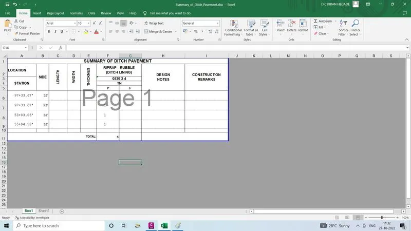
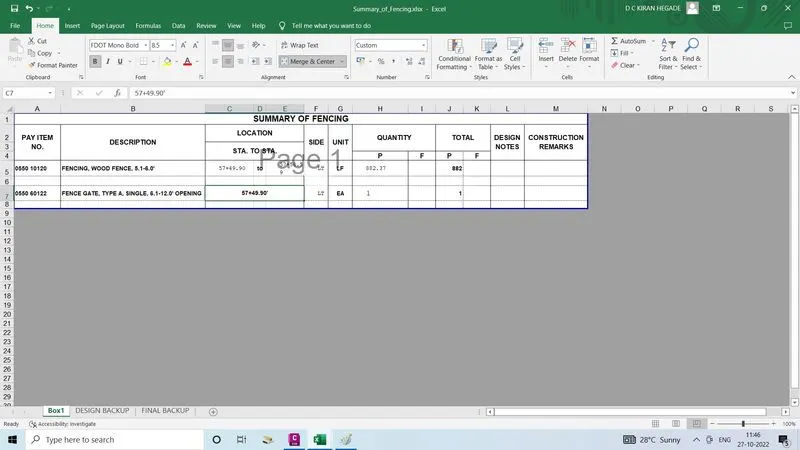
- Copy all praticular quantites and paste it into the particular excel sheet
- Enter in the excel in a properly witha neet

- Open the SUMMRD01 file in the civil3D
- Go to file ,click on open ,Select the SUMMRD01 file which is already exist ,clcik on open
- Click on the tables, click on tables
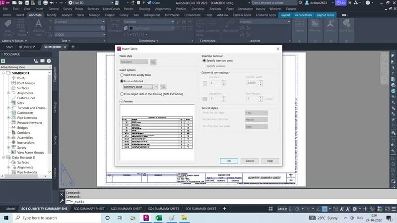
- Make dot mark on from data link
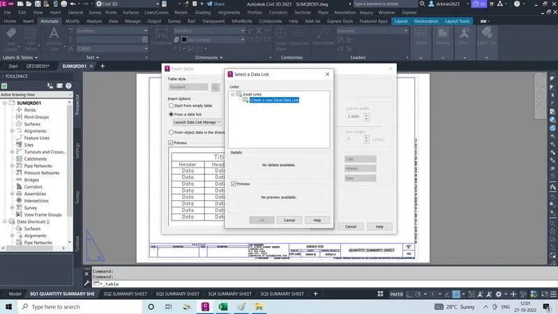
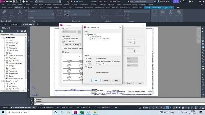
- Click on launch data link manager
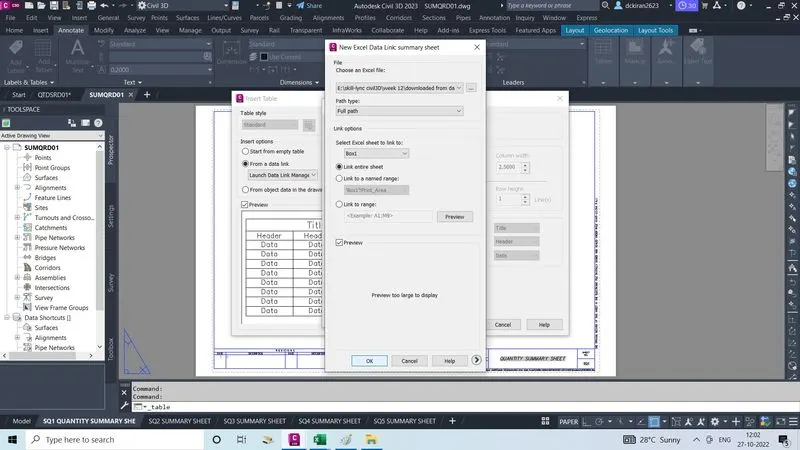
- In data link table click on create a new excel data link
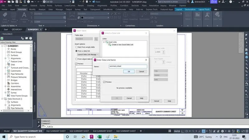
- Enter the name that which data have tom link 1st enter"clearing and grubbing"
- Click on ok
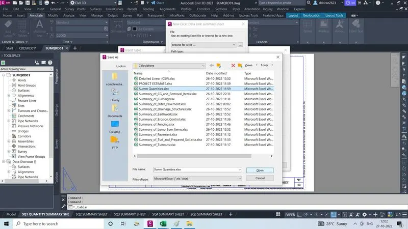
- Brows for a file Select a file go in skill-lync/week12/downloaded from dash board/cadd/calculation /select the excel file which you have to link
- Click on open
- Click ok,ok,ok
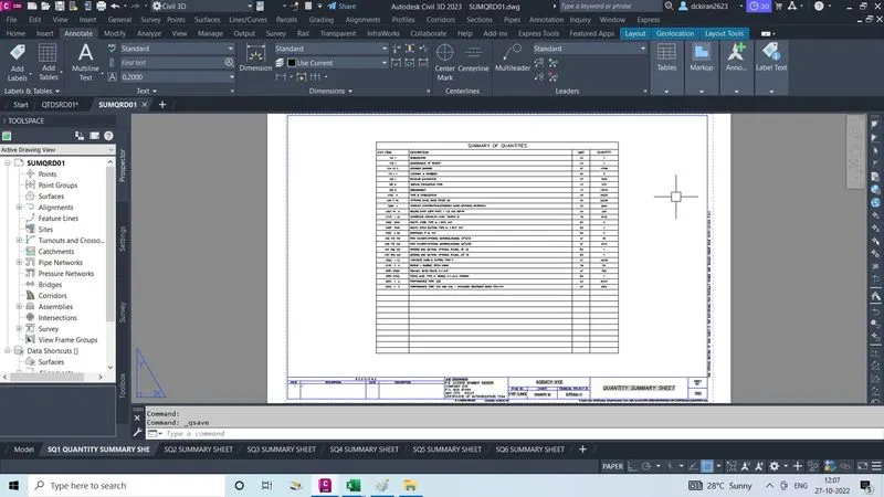
- Place it on the summary sheet layouts
- Like wise do the same procedure for all quantites which are said by the company
- All layouts is created
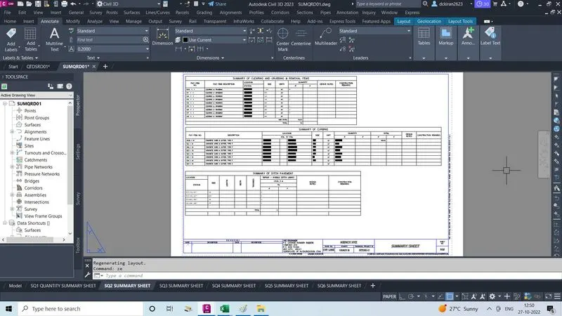
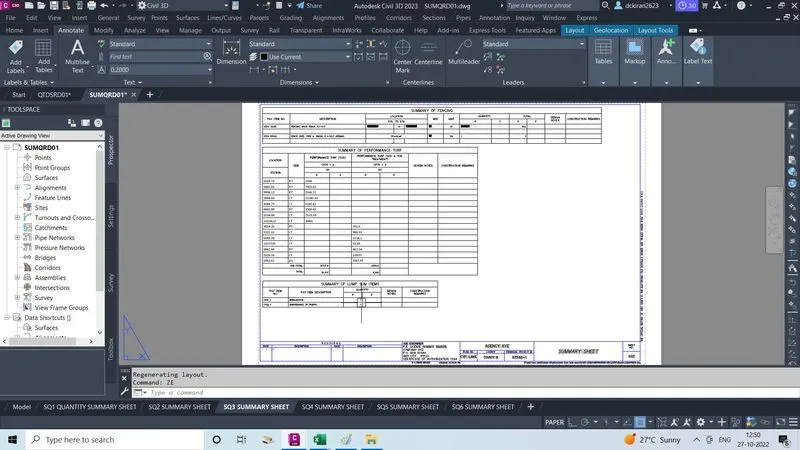
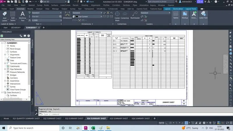
- After creating all the layouts
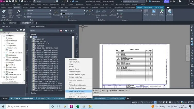
- Select all the layouts and right click
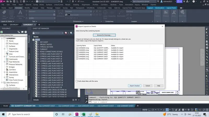
- Click on import layout sheet
- Select and click on import checked
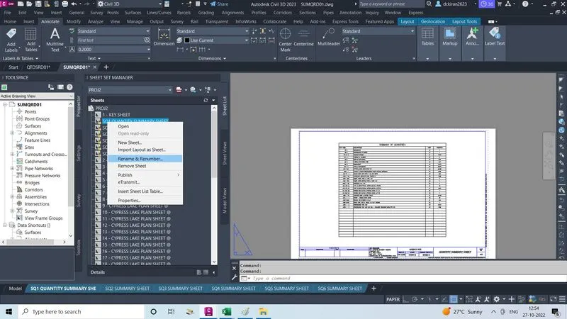
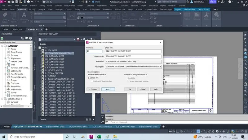
- Select and right click on sheets,Click on the rename and renumber ,give the serial number and edit the name ,click next
- Do the same for all layouts, click ok
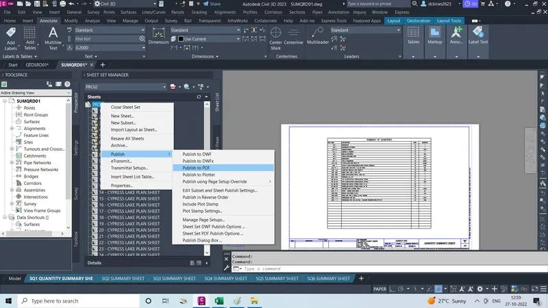
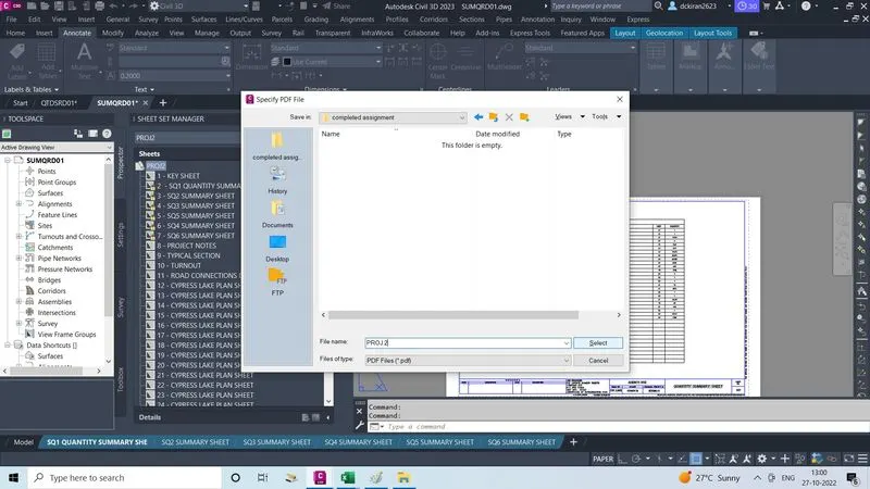
- Last select and right click on the publish
- Click on publish to PDF
- Gve a name of folder store in the proper folder click on select
- It will be converted into PDF and store in the selected folder
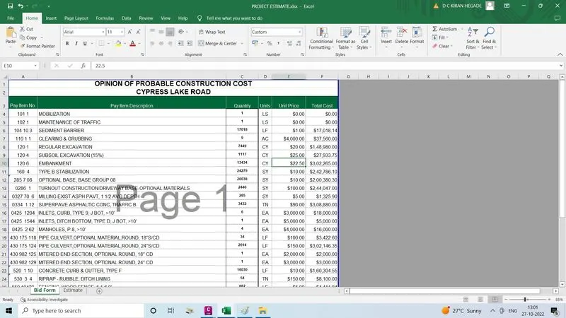
- After entering all the quantites, unit price and total cost in the project estimate
- Copy all and paste into the final form as bidform leave blank in the total cost column and submit it
- The contractor will entire the cost of quantites what they are invested in the road
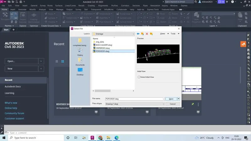
- Open the pond file (PDPLRD01) file civil 3D
- In PDPLRD01 /toolspace/select and right click on site
- Click on new
- Give the name as pond1, click ok
- Subdivisions are reflected in a pond1 like, alignment, feature line,grading groups
- Click on new
- Give the name as POND1ao, click ok
- Create feature line, home/feature line, click on create feature line
- Give name as Top(140), we can give the style, click ok
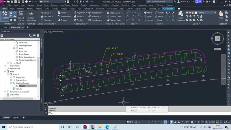
- Now start the grading of pond
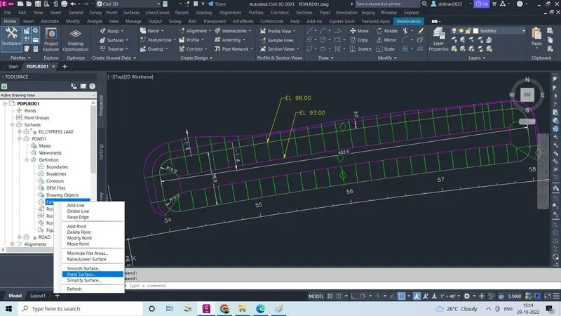
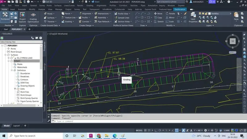
- Next we have to create a surface
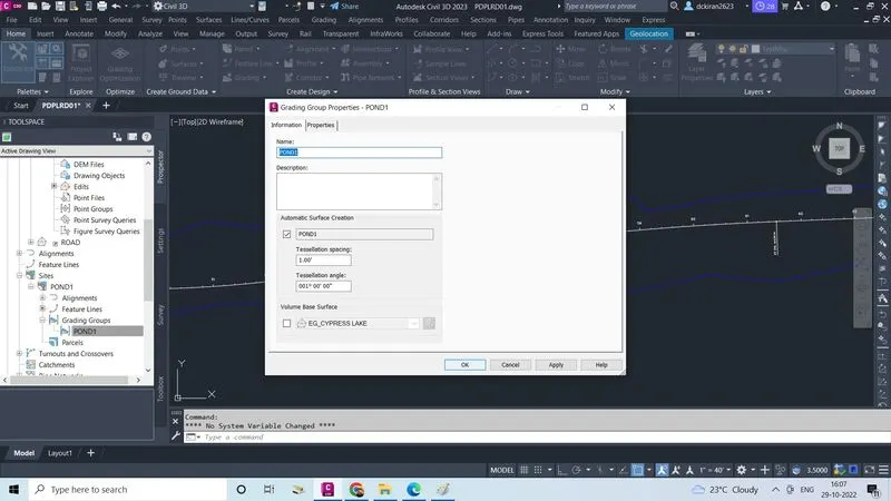
- Select and right on the POND1 click on properties
- Check mark on the tessellation spacing click ok
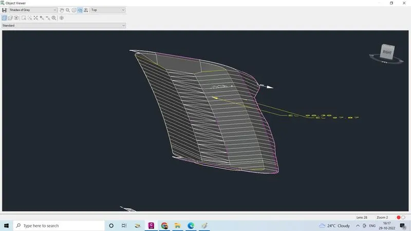
- Now surface is created for pond
- Open the DRPRD01 file in the civil3D
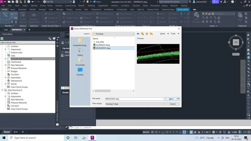
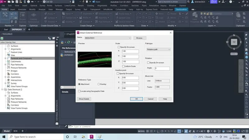
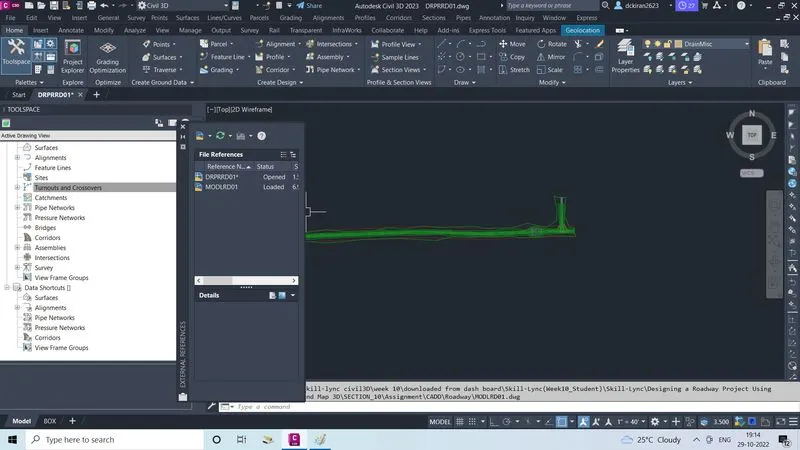
- Export MODLRD01 file into a land xml file and import it into the DRPRD01 file or
- Type command XREF import the MODLRD01 file in the DRPRD01 file
- Now we have to create a pipe network
- Go to home tab, click on pipe network
- Click on pipe network creation tools
- Give the network name as pipestrome(PROJ1)
- Give network parts list strom sewer
- Give the surface name FG
- Select the alignment name
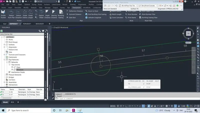
- Click ok, network layout tool will open
- Select the frame as rectangular structure circular frame 48x48 rect two
- Select the concrete pipe of any one 24 inch
- In transparent, select the station offset
- Click on the exact point where we can start to add the pipe network
- Last Click end of the pipe well select the MES
- Place on the edge of the road
- Pipe network is created

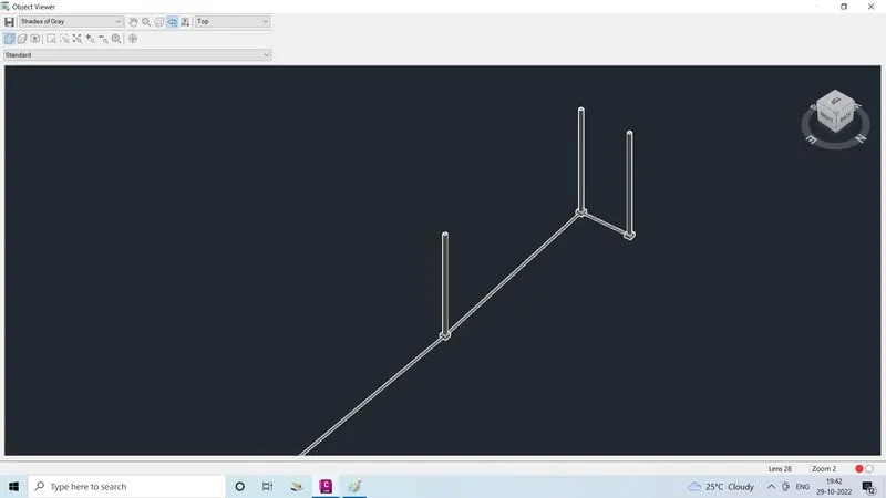
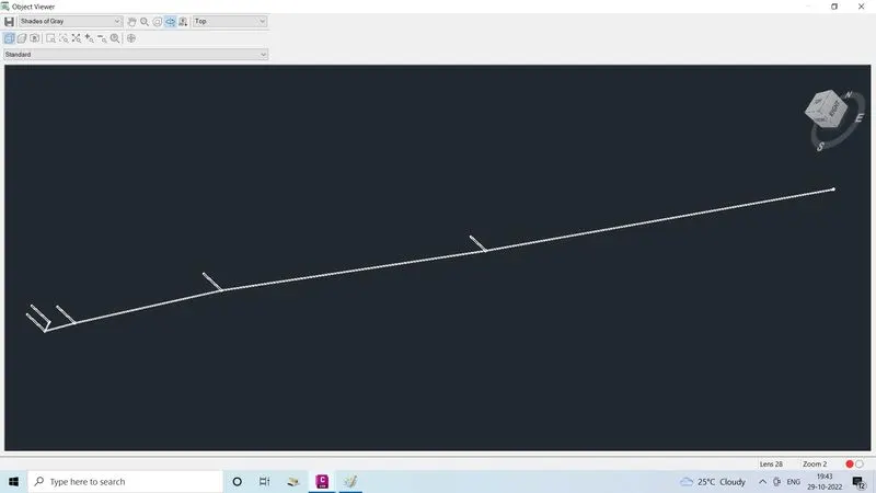
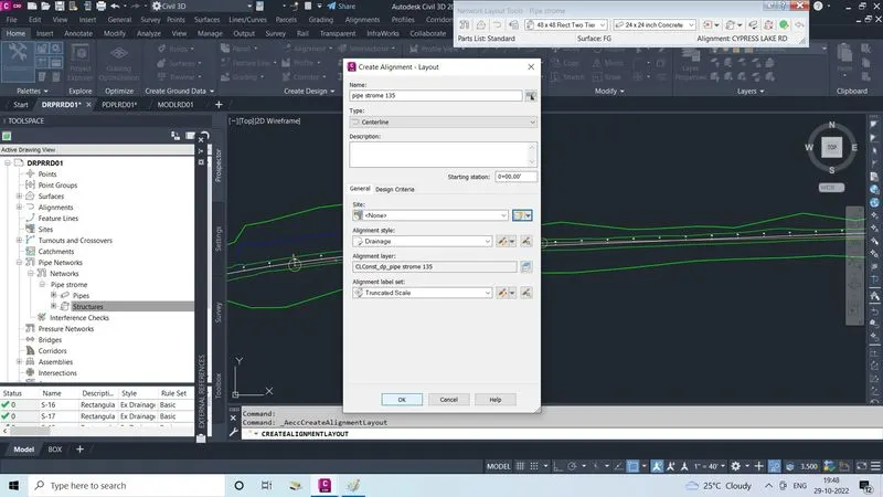
- Click on alignment, click on create alignment from network parts
- Give the name as pipe strome 135
- Start draw an alignment for the pipe
- Alignment is drawn for the pipe to create profile view for the pipe network
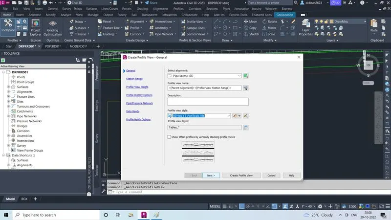
- Click on profile, click on create multiple profile view
- Select the alignment as pipe strom135
- Click next
- Click next
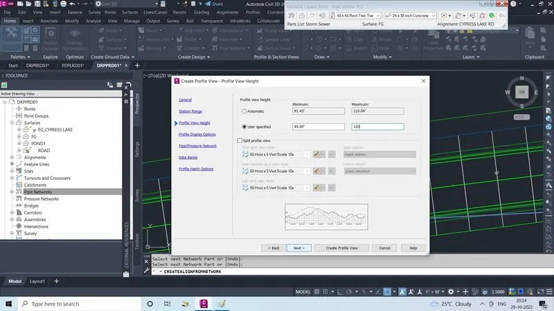
- Dot mark on the user specified give the height
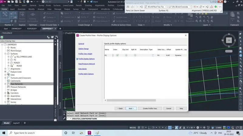
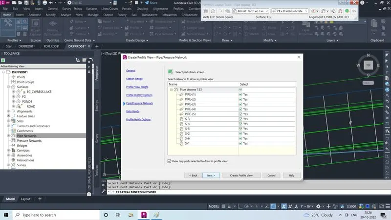
- Click next
- Click on create profile view
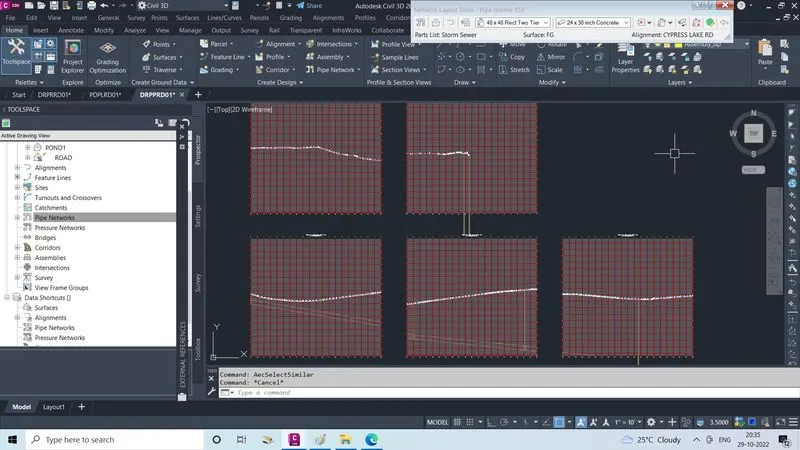
- Click on some where profile view of the pipe network is created
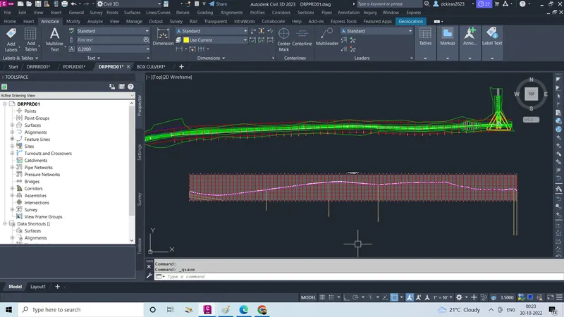
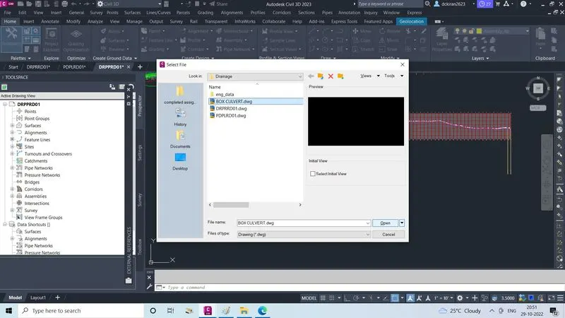
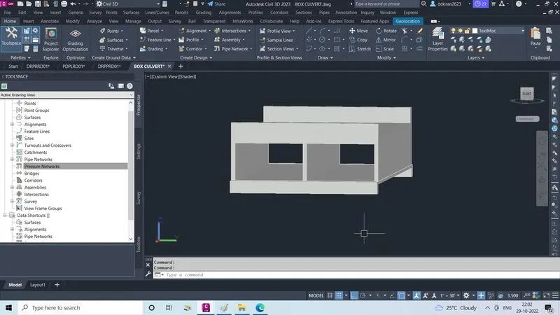
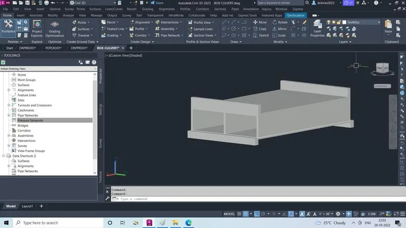
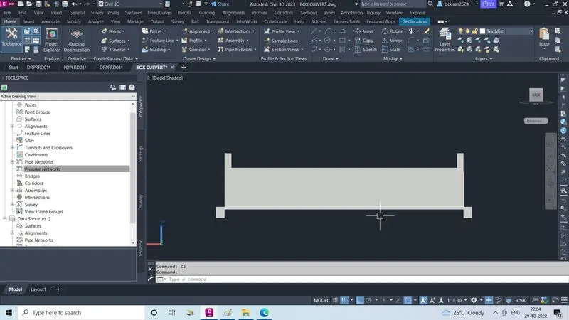
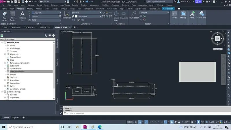
- Open the BOX CULVERT file in the civil3D
- Use regular Autocadd tools to create the Box culvert