Project 2 - Lane National Highway Roadway Design in Civil 3D
Develope the road geometric design for 2lane NH concrete road with paved shoulder for 80kmph design speed from the provided data.
- Creation of surface.
- Alignment & profile design.
- Creation of assembly & subassembly.
- corridor development.
- Section line & detail cross section.
Develope the road geometric design for 2lane NH concrete road with paved shoulder for 80kmph design speed from the provided data.
- Creation of surface.
- Alignment & profile design
- Creation of assembly & subassembly.
- corridor development.
- Section line & detail cross section.
1.Creation of surface. To create a surface first we have to create a file
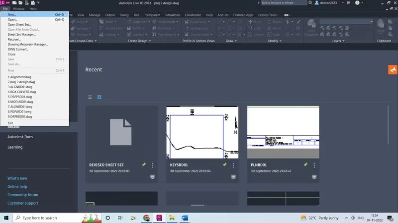
- Go to file
- Click on new
- Select one template file which is provided by the company called skill-lync project 2. dwt file
- Click on open
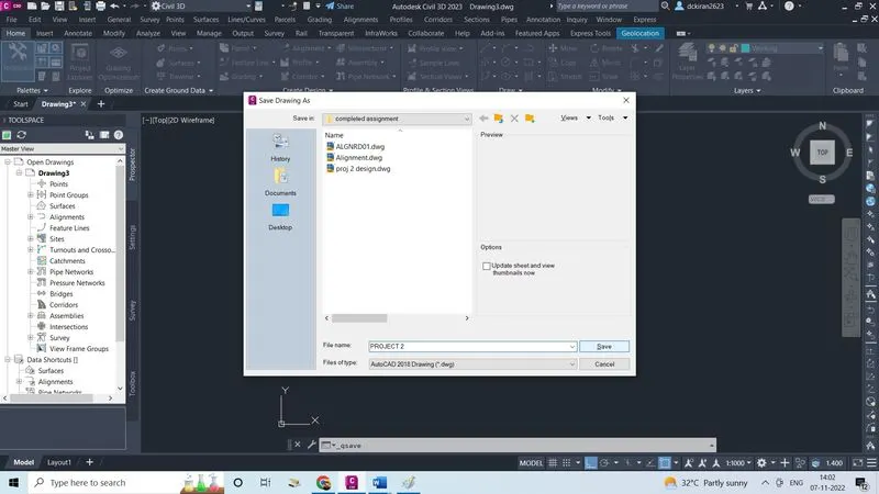
- Type comand CTRL+s to save the file give the name as PROJECT 2 save in a proper folder(skil-lync/geometric design fundamental/completed assignment)
- Click save
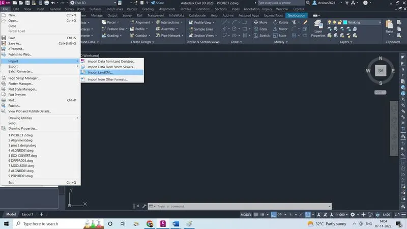
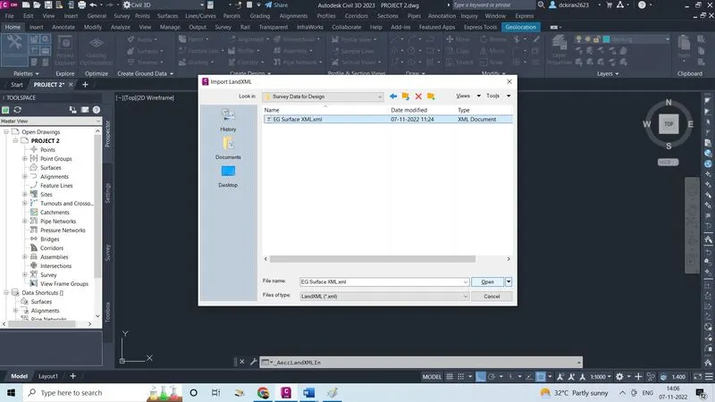
- Go to file, click on import to land xml
- Import the EG surface xml which is provided by the company
- Click on open
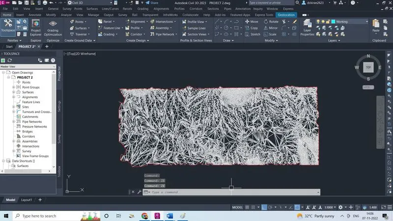
- Surface is created
2.Alignment & profile design: Now i have to create an alignment
- Go to home tab
- Click on the alignment
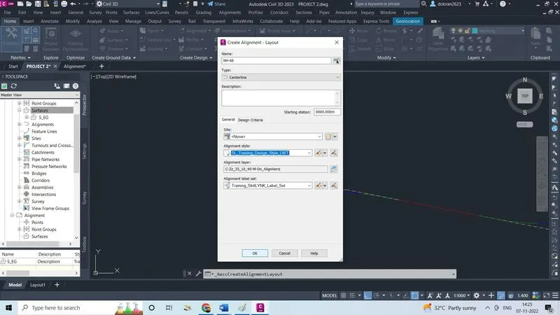
- Click on create alignment by layout
- Give the alignment name as NH-66
- Click on ok
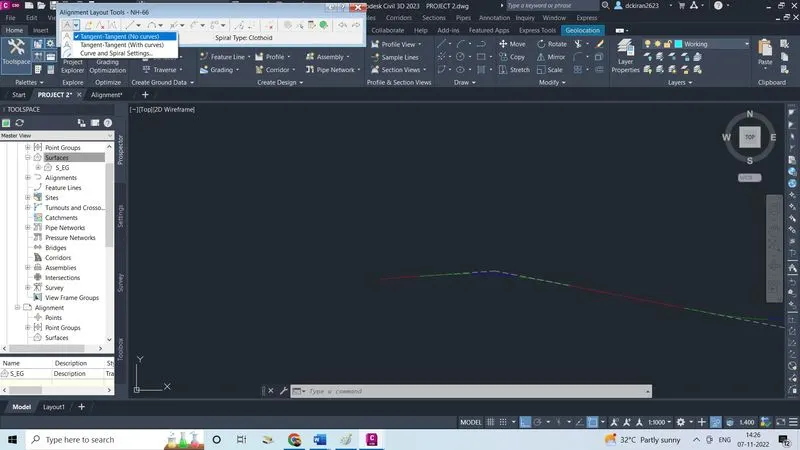
- In alignment tool box select the tangent tangent (no curve) and start to draw the alignment
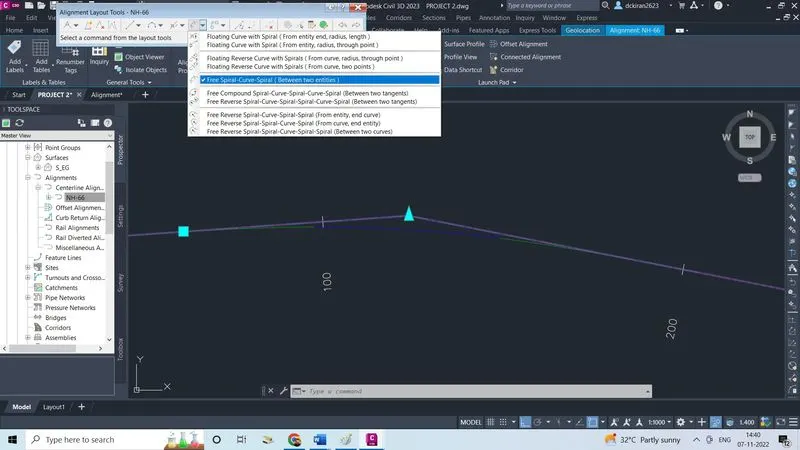
- Select the first entity and second entity enter give the radius 400m click enter , give the transition lenght is 55 as per the standard
- Then select first entity and second entity enter, give the radius 250 enter , give the transition lenght is 90 as per the standard
- Alignment is created
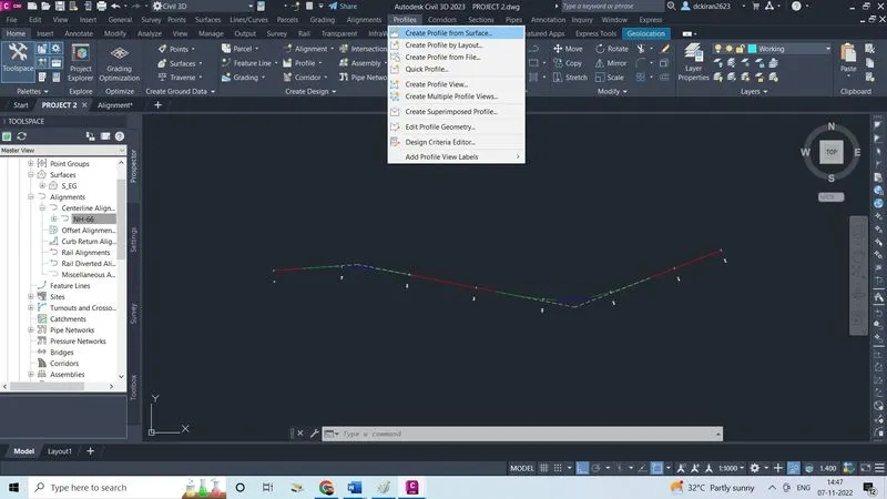
- Now we have to create profile
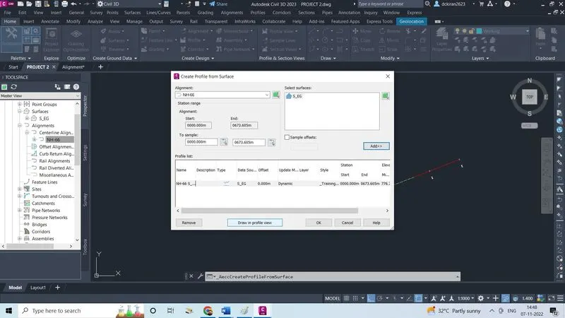
- Select alignmnet and select surface , click on add
- Click on draw in profile view, after that
- Select an alignment, give the profile view name as NH-66 click next
- Click next
- Activate user specifed guve the minimum and maximum height
- Click next, click next
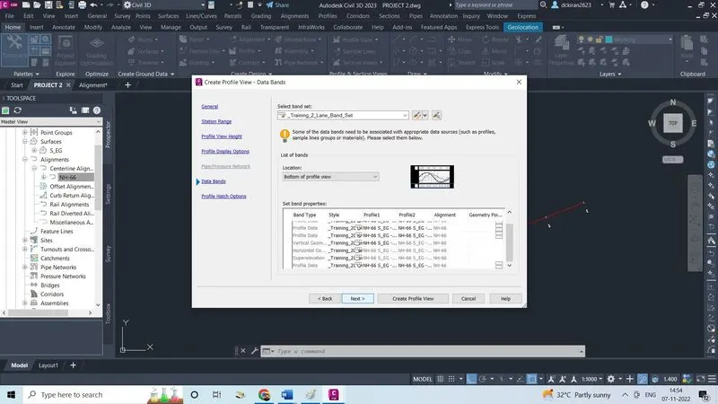
- Select band set as training-2-lane-bant set,click next
- Click on create profile view
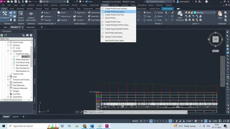
- Now Click on the profile and click on create profile by layout and select profile
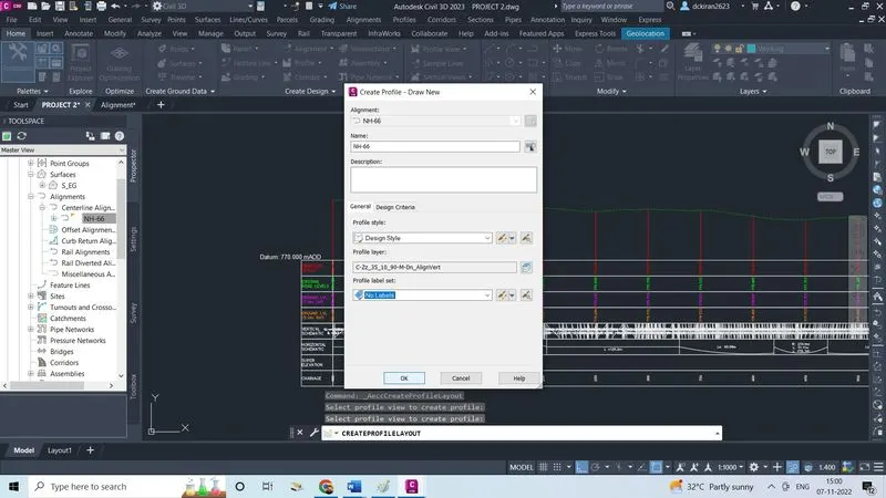
- Give name as NH-66 we can change profile layer and label set,after, Click ok
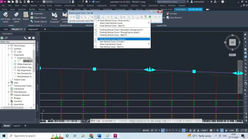
- Click on draw tangent and draw the tangent from begining to end
- Click on free vertical curve(parabola) to find the K value
- Now file profile and profile view is created
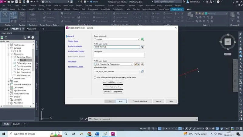
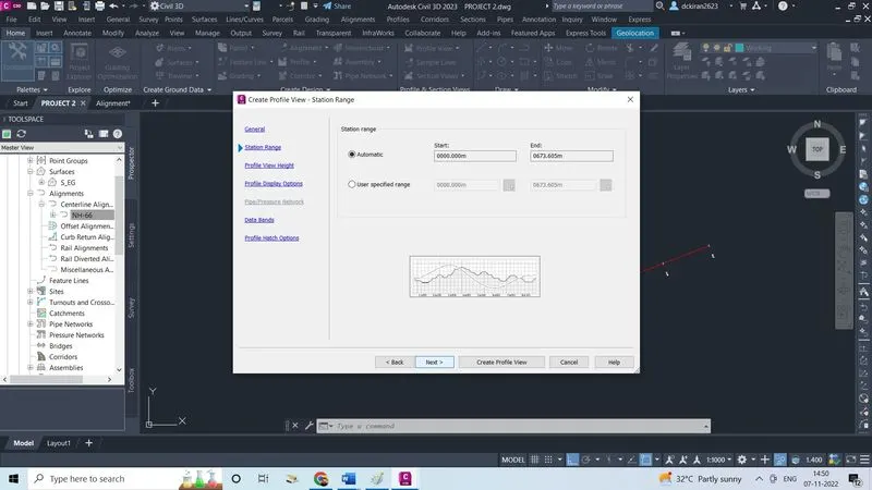
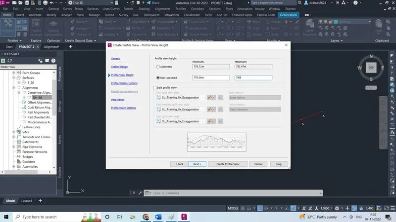
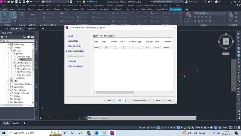
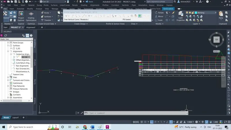
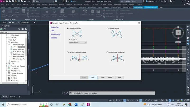
3.Creation of assembly & subassembly. Now we have to create assembly and subassembly
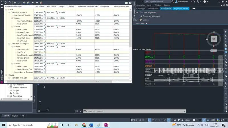
- Before that calculate super elevation
- Select an alignnent, click on super elevation, Click calculate/edit super elevation
- Select undivided crowned , enter the lane width and slope as per standard
- Enter the shoulder width and slope is 2.5m and 3% as per standard , click next
- Click finish
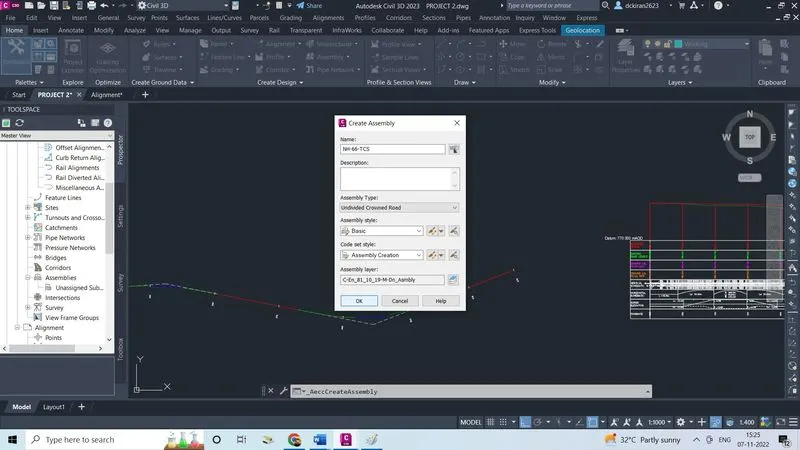
- Now go to home tab, Click on assembly click on create assembly
- Give the name as NH-66TCS select assembly type ,Click ok
- Type Command MT to give the name of assembly type CTRL+F select name object click ok
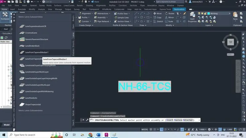
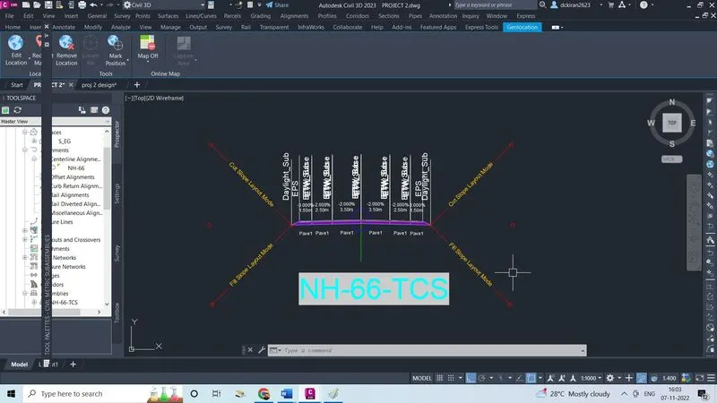
- Select the assembly click on tool palet add the lanes on both side as per the standard
- Select the assembly click on tool palet and add the paved shoulders 2.5 both sideas per standard
- Select the assembly click on tool palet and add the earthen shoulder 1.5 both side
- Assembly is created with a proper width and slope
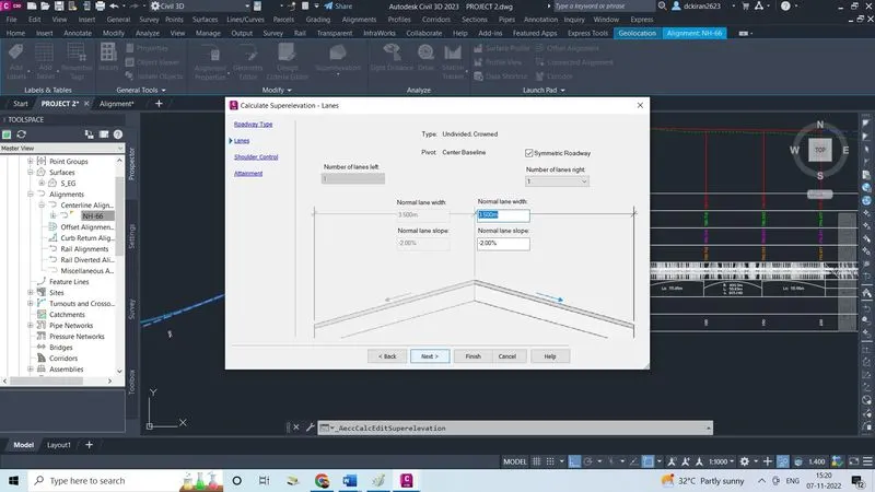
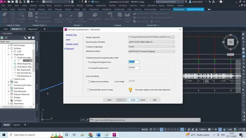
4.corridor development. Now we have to create a corrdor
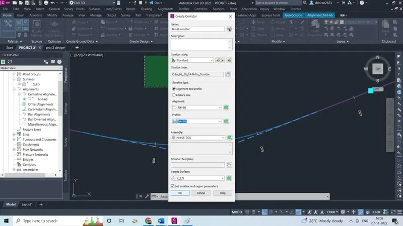
- Click on corridor, click create corridor
- Give a name, select the alignment, select the profile Select the assemly, Select the target surface
- Click ok
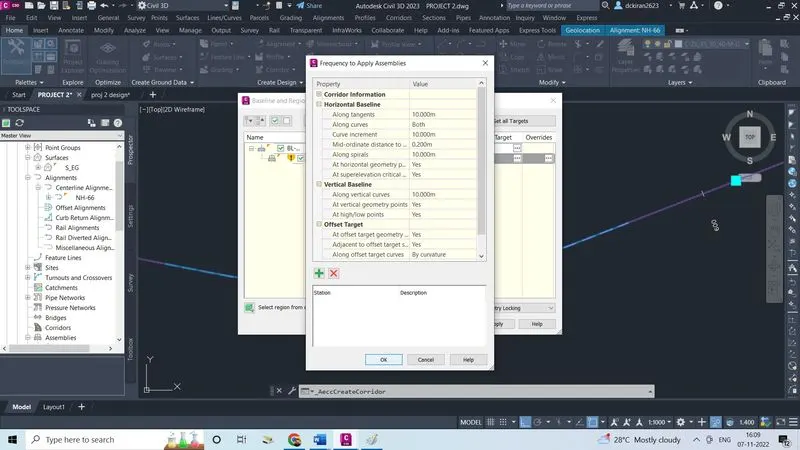
- Set the frequeny , set the target, select the surface to all target, Click ok
- Click apply and ok after that
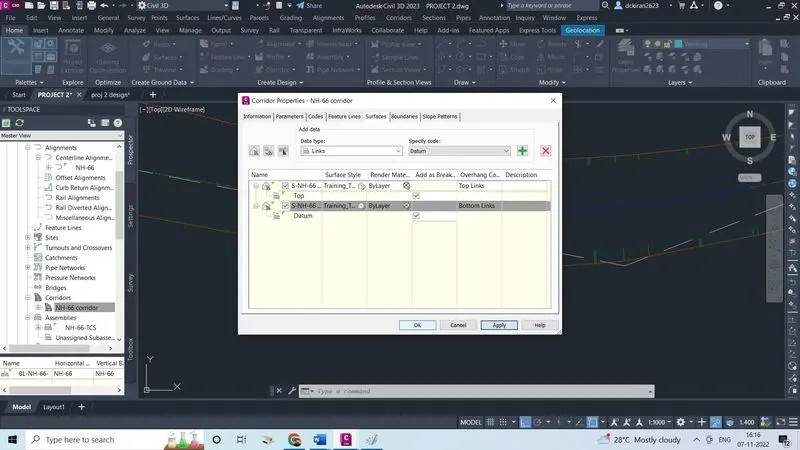
- In toolspace select and right click on the corridor
- Click on properties one dailog box will open in that
- Go in the surface add the top and dattum surface
- Check mark on both select the over hanging top and bottom links
- Click apply and ok
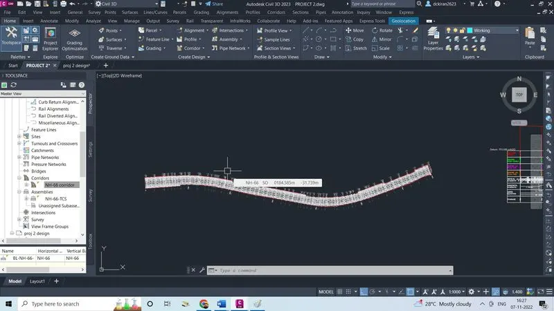
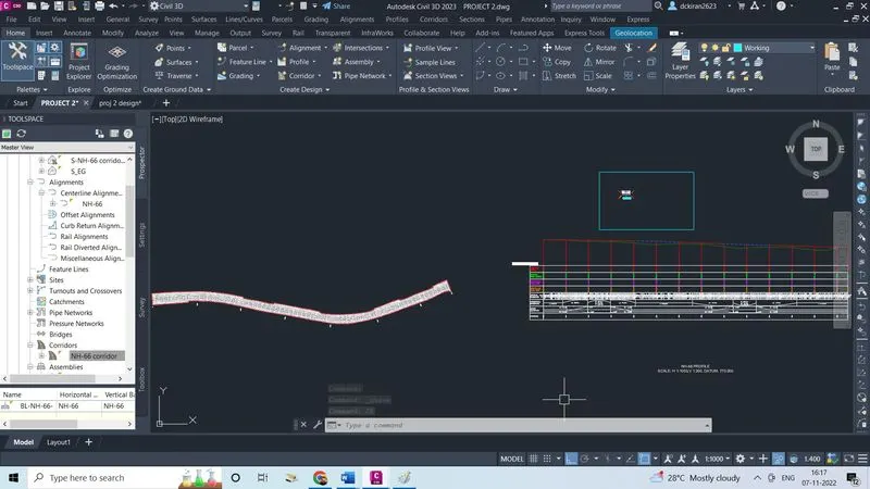
- Corridor is created
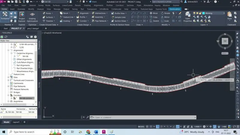
5.Section line & detail cross section. Now we have to create the cross-section and details so
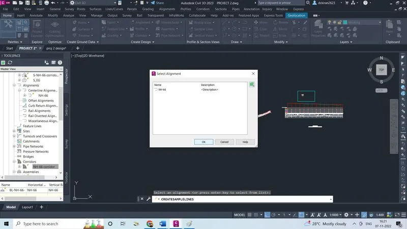
- Go to menu bar click on section, click on create sample lines and pres enter
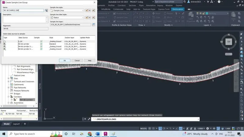
- Click ok
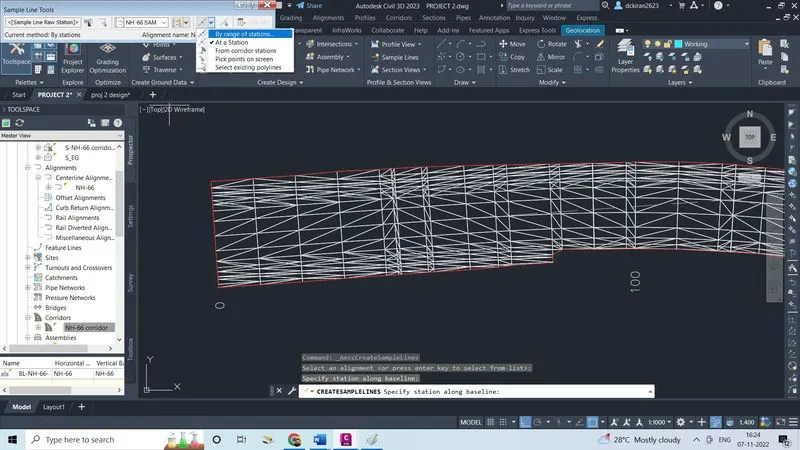
- Sample line toolbox will open select station by range
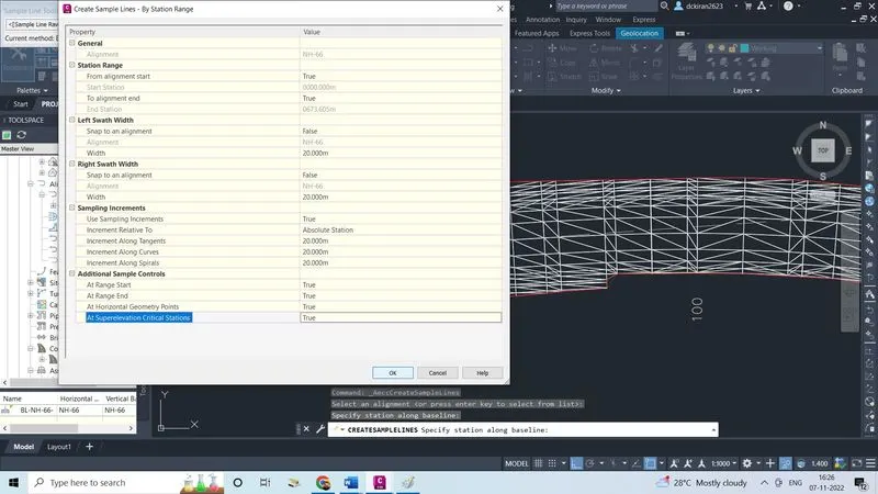
- Fill all the followings Mention the width, click ok
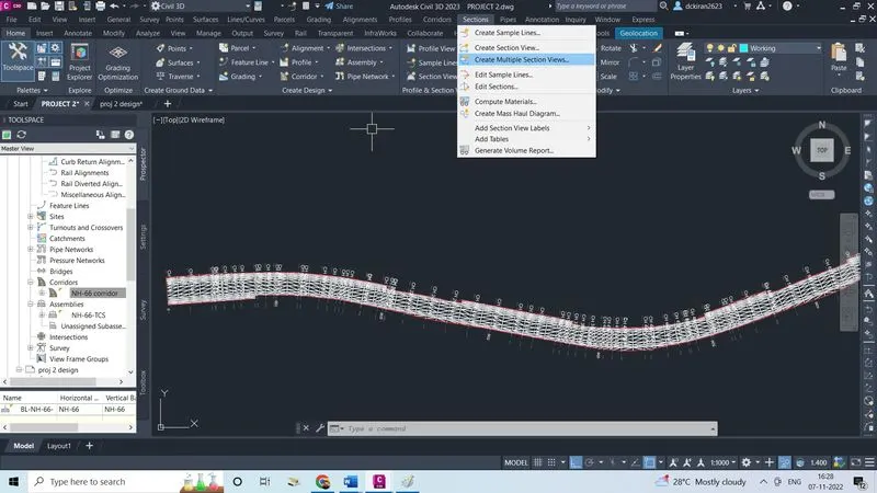
- Sample lines are created
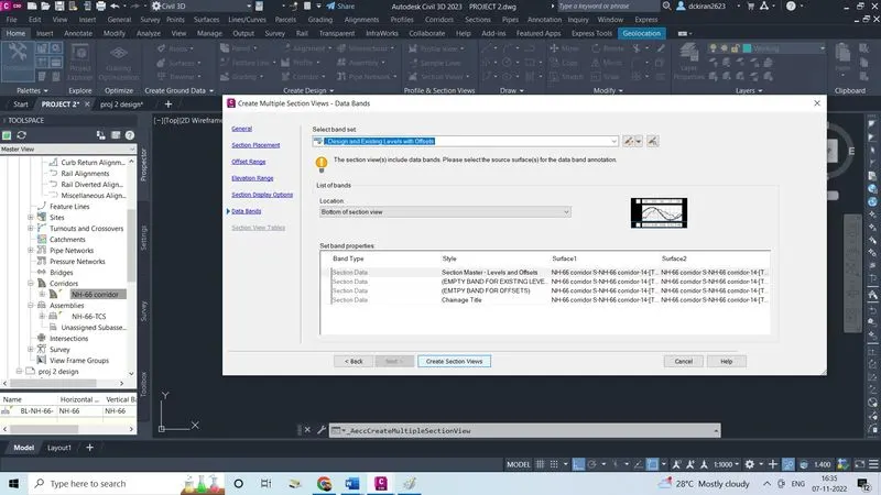
- Click on the section, Click on the create multiple section views
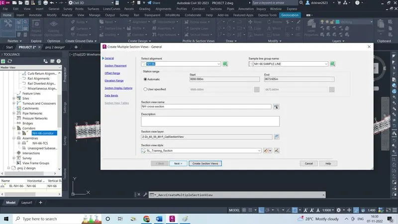
- Select the alignment, Select sample line group name
- Station range is done
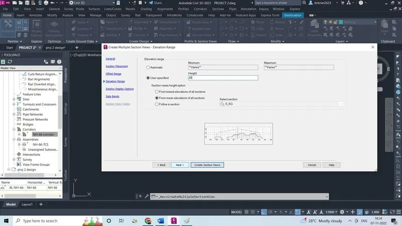
- Give section View name , click next, click next
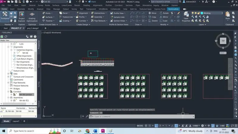
- Click create section view
- Cross-section view is created with detailed